Wednesday, 29 March 2017

Simple LED Driver Design


The Simple LED Driver Design TCA62735AFLG is a charge pump type DC DC Converter specially designed for constant current driving of white LED. IC can outputs LED current 120mA or more to 2.8-4.2V input. IC observes the power-supply voltage and the output voltage, and does an automatic change to the best of step up mode 1, 1.5 or 2 times. It is possible to prolong the battery longevity to its maximum.This IC is especially for driving back light white LEDs in LCD of PDA, Cellular Phone, or Handy Terminal Equipment.


This electronic project t LED driver is very simple and require few external electronic parts. Due of simplicity of this circuit this project not require additional explanations . If you want to change this design , please consult the manufactured datasheet.

Some features of the TCA62735AFLG electronic project are Switching Frequency : 1MHz(Typ.), Output Drive Current Capability : Greater than 120mA , 4 Channels Built in Constant Sink Current Drivers, Sink Current Adjustment by External Resistance, Soft Start Function , Integrated protection circuit TSD (Thermal Shut Down) .

Readmore → Simple LED Driver Design

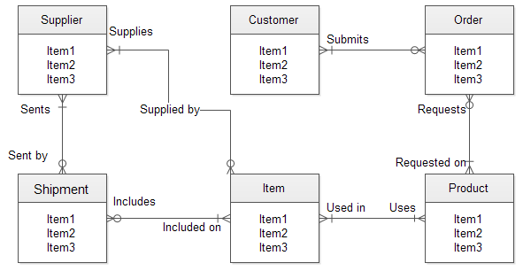
ENTITY RELATIONSHIP DIAGRAM


An entity–relationship diagram ...


entity relationship diagram


Entity Relationship Diagram


entity relationship diagram


entity relationship diagram


entity relationship diagram


Entity-Relationship diagram


entity relationship diagram


Entity Relationship Diagram


entity relationship diagram


... Entity-Relationship ...


entity relationship diagram


Entity Relationship Diagrams


entity relationship diagram


Entity Relationship Diagram


entity relationship diagram


Entity-Relationship Diagram ...


entity relationship diagram


ER Diagram Template


entity relationship diagram


Readmore → ENTITY RELATIONSHIP DIAGRAM

Telephone line Based Audio Muting and Light On Circuit


Telephone line Based Audio Muting and Light-On Circuit. Very often when enjoying music or watching TV at high audio level, we may not be able to hear a telephone ring and thus miss an important incoming phone call. To overcome this situation, the circuit presented here can be used. The circuit would automatically light a bulb on arrival of a telephone ring and simultaneously mute the music system/TV audio for the duration the telephone handset is off-hook. Lighting of the bulb would not only indicate an incoming call but also help in locating the telephone during darkness.
.
Circuit diagram :
Telephone line Based Audio Muting and Light-On Circuit Diagram Telephone line Based Audio Muting and Light-On Circuit Diagram 
.
On arrival of a ring, or when the handset is off-hook, the inbuilt transistor of IC1 (opto-coupler) conducts and capacitor C1 gets charged and, in turn, transistor T1 gets forward biased. As a result, transistor T1 conducts, causing energisation of relays RL1, RL2, and RL3. Diode D1 connected in antiparallel to inbuilt diode of IC1, in shunt with resistor R1, provides an easy path for AC current and helps in limiting the voltage across inbuilt diode to a safe value during the ringing. (The RMS value of ring voltage lies between 70 and 90 volts RMS.) Capacitor C1 maintains necessary voltage for continuously forward biasing  transistor T1 so that the relays are not energised during the negative half cycles and off-period of ring signal. Once the handset is picked up, the relays will still remain energised because of low impedance DC path available (via cradle switch and handset) for the in-built diode of IC1. 

After completion of call when handset is placed back on its cradle, the low-impedance path through handset is no more available and thus relays RL1 through RL3 are deactivated. As shown in the figure, the energised relay RL1 switches on the light, while energisation of relay RL2 causes the path of TV speaker lead to be opened. (For dual-speaker TV, replace relay RL2 with a DPDT relay of 6V, 200 ohm.) Similarly, energisation of DPDT relay RL3 opens the leads going to the speakers and thus mutes both audio speakers. Use ‘NC’ contacts of relay RL3 in series with speakers of music system and ‘NC’ contacts of RL2 in series with TV speaker. Use  ‘NO’ con-tact of relay RL1 in series with a bulb to get the visual indication. 


Author : Dhurjati Sinha - Copyright : EFYmag

Readmore → Telephone line Based Audio Muting and Light On Circuit

Apple i Pods


Dear freinds you know about i pods ?I pods had been since their beginning in 2001, Apple iPods have been the product of choice for individuals who listen to digital music. Recently, Apple has branched out & allowed their iPods to display pics & play videos, but the music aspect of this digital media player is what lures hoards of people in to the Apple stores to buy an iPod.

Its simple design and large memory capacity have been defining features since the first generation. Apple iPods have come a long way since their creation, but despite all of the technological advancement, the basic form and structure has remained very similar. The iPod motif has now been emblazoned on separate pieces of hardware, including the video iPod, the incredibly little iPod Nano and the entry level iPod Shuffle. Each version is a separate entity, but each fills a niche wanted by consumers.

Starting with the iPod Shuffle, you have the lowest priced of all Apple iPods. It lacks an LCD screen and the famous touch wheel that gives you control over all of the other iPod products. In lieu you upload your play lists to the Shuffle and are given the choice to either listen to them in regular play mode or shuffle mode. The iPod Shuffle is available in sizes, gigabyte and half a gigabyte, meaning you can have up to hundred and fifty songs.

The next step up is the iPod Nano. This is the smallest of the actual Apple iPods. It contains a full color LCD screen which can be used to navigate through songs or display photographs. It is available in black or white and comes in a variety of memory sizes all above gigabyte. As an added bonus, it contains the new version of the iPod operating technique, giving you powers historicall the past bestowed only to Mac computers. At around a quarter of an inch thick and an ounce and a half in weight it is ideal for taking to the gym.

Finally, they have the granddaddy of all of the Apple iPods  the fifth generation video iPod. This iPod has a giant full color screen to show songs, pics, tv shows, movies and video podcasts. Clocking in between thirty and sixty gigabytes, you can store songs and videos on this iPod to last you through a flight around the globe.

Readmore → Apple i Pods

Tuesday, 28 March 2017

A Car Battery Monitor Circuit Diagram


A close call on the road can really focus your mind on the importance of having a battery monitor in a car. I had been enjoying a pleasant week of travelling around the countryside at a leisurely pace and taking in the beautiful scenery each day. It wasn't until the final day, with the big rush to return home, that I had to drive at night.My home is deep in the country and on the road I was travelling the closest petrol station may be 80km away. I was travelling through an area that is full of open-cut coal mines and large heavily loaded semi-trailers constantly pound the roads, travelling at quite high speeds. It was around 8pm at night and everything was very dark no street lights or house lights anywhere.

Just as I was going up a hill, the lights began to dim and the engine coughed. A large semi-trailer loomed in the rear-vision mirror as I pushed the clutch in and tried to restart. My speed was falling rapidly and my lights were blacked out - I was like a sitting duck in the middle of the road, as the semi-trailer came rapidly bearing down on me. I just managed to pull the car off the road, as the semi-trailer came screaming past, missing me by inches! After calling for assistance from the NRMA, the problem was found to be a fault in the alternator, which was failing to charge the battery. The battery voltage had been falling under the heavy load of the lights and at the worst possible time, there was not sufficient power for the lights or the motor.


After the initial shock wore off, I put on my thinking cap to come up with a PIC-based solution to the problem. What was really needed was a display and a buzzer, to get my attention should the voltage fall outside a specified range. So my design criteria was set, a series of LEDs could indicate the voltage and a buzzer would also be used to warn of problems.
Main Features:
  • Visual indication of battery voltage
  • Audible warning when voltage becomes low
  • Screw terminals for easy connection
  • Simple and easy to build
Circuit details:

The circuit is based on PIC16F819 18-pin microcontroller which has an analog-to-digital (A/D) input to monitor the battery voltage and outputs capable of driving LEDs directly, to keep the component count down. There are seven LEDs in all, giving a good range of voltage indication. The topmost LED, LED1, comes on for voltages above 14V which will occur when the battery is fully charged. LED2 indicates for voltages between 13.5V and 14V while LED3 indicates between 13V and 13.5V. Normally, one of these LEDs will be on. LED4 covers 12.5V to 13V while LED5 covers 12V to 12.5V. LED6 covers from 11.5V to 12V while LED7 comes on for voltages below 11.5V. These two LEDs are backed up by the piezo chime which beeps for voltages between 11.5V and 12V and becomes more insistent for voltages below 11.5V.

That might seem fairly conservative. After all, most cars will start with no troubles, even though the battery voltage might be a touch below 12V, won't they? Well, no. Some modern cars will happily crank the motor at voltages below 11V but their engine management will not let the motor start unless the voltage is above 11V. So don't think that a modern car will always start reliably. This little battery monitor could easily prevent a very inconvenient failure to start! So let's describe the rest of the circuit. The incoming supply is connected via diode D1 which provides protection against reverse polarity while zener diode ZD1 provides protection from spike voltages.

A standard 7805 3-terminal regulator is then used to provide a stable 5V to the microcontroller. The battery voltage is sensed via a voltage divider using 33kΩ and 100kΩ resistors. This brings the voltage down to within the 0-5V range for the A/D input of the PIC16F819. Port B (RB0 to RB7) of the microcontroller is then used to drive the various LEDs, with current limiting provided via the 330Ω resistor network. RB7, pin 13, drives a switching transistor for the piezo buzzer.

Software:
For the software, the design follows the basic template for a PIC microcontroller. Port A and its ADC (analog-to-digital converter) function are set up while port B functions as the output for the LEDs and buzzer. Once the set-up is complete, a reading will be taken at port RA2, the input for the A/D convertor. This reading is then compared with a series of values to determine the range of the voltage. This is similar to a series of "if" statements in Basic language. If the voltage is found to be within a certain range, the relevant port B pin will be turned on. If the voltage is below 12V, the buzzer will be turned on for a brief period, to signal a low battery condition. As the voltage falls below 11.5V, the frequency of the beeps will increase, to signal increased urgency.

Building it:

All the parts are mounted on a small PC board measuring 46 x 46mm (available from Futurlec). The starting point should be the IC socket for the PIC16F819, as this is easiest to mount while the board is bare. The next item can be the PC terminal block. The resistors and capacitors can then follow. Make sure the electrolytics are inserted with correct polarity.

Make sure that you do not confuse the zener (ZD1) with the diode when you are installing them; the diode is the larger package of the two.
Even more important, don't get the 78L05 3-terminal regulator and the 2N3906 transistor mixed up; they come in identical packages. The 78L05 will be labelled as such while the 2N3906 will be labelled "3906". And make sure you insert them the correct way around. The buzzer must also be installed with the correct polarity. The 330Ω current limiting resistors are all in a 10-pin in-line package. There are four green LEDs, two yellow and one red. They need to be installed in line and with the correct orientation.

Testing:

Before you insert the PIC16F819 microcontroller, do a voltage check. Connect a 12V source and check for the presence of 5V between pins 14 & 5 OF IC1. If 5V is not present, check the polarity of regulator REG1 and the polarity of the diode D1. If these tests are OK, insert the IC and test the unit over a range of voltage between 9V and 15V. Make sure that all LEDs come on in sequence and the piezo buzzer beeps for voltages below 12V. 

Now it is matter of installing the unit in your car. It is preferable to install the unit in a visible position for the driver. However, it should not obscure any other instruments. The unit should be connected to the car's 12V supply after the ignition switch. This will turn the unit off with the other instruments and prevent battery drain while the motor is not running.


Author :Alan Bonnard

Readmore → A Car Battery Monitor Circuit Diagram

CL21N11MJZXXAX Samsung DIGITAL TELEVISION RECEIVER Circuit diagram Chassis KS9A N


Used ICs: TDA9352PS/N21/3-OTP, 24C04, LA6510, 346VF2(Infrared sensor), KA5Q0765R | KA5Q0740RT(120v) | KA5Q0765RT (220V), KA7632, FCA173B(FBT), NJM2235D, AN7522N, MSP3425G-B7 and TDA6107Q [NTSC system – North America, South Central America and Mexico]
FOCUS Adjustment
1. Input a black and white signal.
2. Adjust the tuning control for the clearest picture.
3. Adjust the FOCUS control for well defined scanning lines in the center area of the screen.
Factory Adjustment
To enter the “Service Mode”, Press the remote-control keys in this sequence :
- If you do not have Factory remote-control
Picture OFF > Mute > 1 > 8 > 2 > Picture ON
- If you have Factory remote-control
Picture ON > Display > Factory
Circuit diagram
Click on the circuit diagrams to magnify


Readmore → CL21N11MJZXXAX Samsung DIGITAL TELEVISION RECEIVER Circuit diagram Chassis KS9A N

Simple LED light Organ Circuit Diagram


This is a Simple LED light Organ Circuit Diagram. This is a fun circuit that can be at parties, for example. The four LEDs flash to the beat of the music. The light organ responds using a microphone to sound.T1 amplifies the signal from MIC. The sensitivity can be adjusted by P1. T4 controls the LEDs. 

These are preferably LED's with a high light intensity.MIC is a condenser microphone. The circuit can be powered by a 9 V battery.

 LED light Organ Circuit Diagram

 LED light Organ Circuit Diagram


The 4 Budget

This circuit costs about € 6.15.


Parts List

  •      R1 = 10 k
  •      R2 = 330 K?
  •      R3, R6, R13 = 100 k
  •      R4, R8, R11, R14 = 47 Ω
  •      R5, R9, R12 = 1.5 MΩ
  •      R7, R10 = 47 k
  •      P1 = 220 K?
  •      C1, C2, C3 = 100 nF
  •      C4 = 100 uF
  •      D1-D4 = LED
  •      T1, T2, T3 = BC547B
  •      T4 = BC557B
  •      MIC = microphone capsule

Readmore → Simple LED light Organ Circuit Diagram

Monday, 27 March 2017

parabolic solar collector


Readmore → parabolic solar collector

Sunday, 26 March 2017

Emergency Light Flashlight


 3 in 1 - LED Night Light, LED Emergency Light and LED Flashlight; Length: 4.0". The Night Light has an Automatic Sensor which allows On at Dusk and Off at Dawn. The Emergency Light features an 8 Hour Battery Back Up. Convenient White Light Flashlight.
The light is not terribly sharp-witted but it's first-class sufficient to facilitate you won't be real bumping into furniture all through a power outage. The light is by the side of its brightest at what time the power is rotten.
When its used having the status of a nightlight it is a not much dimmer but still upbeat adequate to perceive your way around.


Emergency Light, & Flashlight
The intensity of the light motivation vary depending on how dark the opportunity is. during the belatedly afternoon while the sun is still outside it will live very dim but will perk up up being the extent becomes darker. Although here is a photo sensor on the light a loss of power preference aim the light on in spite of of how dark before light the area is.

The light stays on a bunch longer than the circular emergency plug concerning illumination with the aim of I've used in the older and it looks a lot better than them. I carry out think it would look even better devoid of the flashlight part of the light and I would have a preference to grasp a version like with the aim of if they'd offer it.

Once plugging into a lookalike outlet it still leaves area intended for a lesser plug to progress into the outlet then to it. 

Readmore → Emergency Light Flashlight

Simple low high voltage cut circuit


Simple low/high voltage cut circuit
Here is a circuit of simple low/high voltage cut circuit.Various safety circuit (low/high voltage cut) using IC.But in this circuit we are using two transistor for this circuit.
As we saw that the entire circuit is build using two transistor and very few of other components.Transistors are used to drive the relay.And also transistor T1 and T2 used to cut the supply in high and low voltage respectively.Where the variable resistors VR1 and VR2 is used to adjust the high and low voltages.As we know that when zener diode is connected to emitter of transistor then it get back bias voltage. The variable resistor VR1 and VR2 is so adjusted that it does not connect the transistor T2 and T1 in high and low voltage respectively. The load is connected through relay RL1.
 
PARTS LIST

Resistors
R1, R4 = 4.7 KΩ
R2, R3 = 220 Ω
VR1 = 10 KΩ
VR2 = 10 KΩ
Semiconductors
T1, T2 = BC148
ZD1, ZD2 = 5.6V
Miscellaneous
RL1 = 18V/500Ω


Readmore → Simple low high voltage cut circuit

Auto Sound Systems One Piece at a Time


Those who are in the market for auto sound systems are probably well aware of the many decisions that need to be made throughout the process. Gone are the days when you went in, pointed to a box and walked out with all the pieces, parts, and components you would ever need for a really kickin' sound. The truth of the matter is that there are many pieces and parts that work together in order to create the ultimate sound system and everyone seems to have different requirements, styles, tastes, and budgets to work with.
Because of this, many manufacturers of auto sound systems have wised up to the fact that some people will buy the components they need to create the sound system of their dreams piece by piece as budgets allow. This is actually a very intelligent way for customers on a budget to buy the sound system they are hoping to some day have. As a result you will find that speakers, amplifiers, sub woofers, and the actual stereo are often sold separately and at very reasonable prices.


Most of us hate living within limited budgets but understand that often in life it is a necessary evil. Living on a budget is not such a terrible thing really. If we had everything we wanted, what on earth would there be to look forward to? At least that is what I keep telling myself. I, however, seem to be the queen of budget living and bargain hunting. I love little more in life than finding a great deal on an item I've had my eye on for quite a while and hate little more than finding it cheaper once I've purchased it. As such, I tend to invest a great deal of time researching any major purchase before taking the plunge. A good auto sound system by this I mean good quality, minimal features is going to run (total package and installation) at least $1,000 with many costing a good deal more than that.


That doesn't mean you need to have a thousand bucks lying around the house in order to begin building your auto sound system. You can buy a decent set of speakers for around $200-$260 if you desire. You can find sets at lower prices, but this is the price for a fairly decent set of speakers that should serve you well. Keep in mind that you could very easily spend a lot more than this on speakers if you aren't careful. Living on a budget means you have to make some sacrifices along the way in order to have the things you want in life. Buy the speakers and have them installed (if you can do it or your know someone who can, this will save a lot of time and money).

Once you have the first component, whichever one that may be (that choice is entirely up to you and largely dependent on your personal tastes and which need replacing worse in the vehicle you own) you can begin saving towards the next. You should also consider asking friends and family (who would like to know what to get you for the holidays) to help you reach your smaller goals along the way. Most people are glad to help with specific items if they know what those items are. The point is that this isn't an all or nothing proposition. Take small steps towards your prize and you will find that you are constantly getting one step closer.


Readmore → Auto Sound Systems One Piece at a Time

Simplest Transformerless LED Drivers


In this post we learn regarding three interesting transformerless power supply circuits for illuminating LEDs from mains that uses minimum number of components


Circuit 1


Simplest Transformerless LED Drivers


A capacitor must be having a rating of more than 200V and should be having dialectic of metallize polyester or poly poplin.

A resistor 1K is employed to limit the in rush current the resistor should be having the wattage value of more than 1Watt.

A diode is connected in anti-parallel to the LED. This diode limits the reverse voltage across the LED. The diode also provides the path for the negative half cycle as the LED is connected to a AC power source.

This particular circuit behaves like a constant current source of 15 to 20mA depending on LED voltage bias and supply line stability with a nominal 60Hz power supply frequency. The circuit 2 is an improvisation over circuit 1 and it enables to glow two LED’s at a time. This gives a color benefit also.

Putting two switches to the series part of individual LEDs can enable the viewer to have three colors.

In this transformerless circuit using the above formula the current can be manipulated by changing the capacitor value. Power LEDs can also be driven directly from AC power source.

Circuit2


Simplest Transformerless LED Drivers


The third circuit employs a zener diode of 5.6 V/1W. The zener diode serves dual purpose. Firstly it acts as a bias of the negative half of circuit like the diodes employed in circuit 1 and 2. Secondly, it acts as a voltage regulator for the LED driver circuit.

This circuit provides 5 Volts steady output with a 30mA current pumping facility. The 1000uF capacitor acts as a ripple suppressor and it allows a moderate ripple of 6% that is 300mV in this case. Employing the third circuit the use can expect better life of the LED. The current limiting capacitor used is 1.5uF at 200Volts.

The capacitor supplies the current to the driver as well it biases the zener to remain active during operation.

Please note that while using any LED it's datasheet should be studied beforehand. In general natural white LEDs, cool white LEDs, warm white LEDs all have a nominal bias voltage of 3.5V DC. But the activation starts at 2 to 2.4V DC.

The highest efficiency of the LED is achieved at 3.5V DC. Optimization of power supply is the highest priority in any LED driver circuit.

Circuit 3


Simplest Transformerless LED Drivers


If a constant voltage supply is provided it is to be notes that the power supply must have minimum ripple content.

The peak of the ripple shall also effect the performance of the LED so far as the junction temperature of the wafer is concerned. However a constant current source is a safest power supply alternative for a LED. A constant current source can achieved in many ways.

A variable power supply that is regulated by a current loop is the general trend. A capacitor in series is obviously the most economic constant current source so far as AC power supply is concerned.

Any fluctuation in the input power might result into the change in the current value,for this purpose,a regulator like 5.6 V zener is a safe practice.

While connecting the LED to the regulator circuit the power capacity of the regulator is to be kept in the mind along with the power requirement of the specific LED.

Readmore → Simplest Transformerless LED Drivers

Saturday, 25 March 2017

Simple Simulated inductor Circuit Diagram


This is the Simple Simulated inductor Circuit Diagram. In the this circuit With a constant current excitation, the voltage dropped across an inductance in-(in creases with frequency. Thus, an active device whose output increases with frequency can be characterized as an inductance. 

 Simple Simulated inductor Circuit Diagram

 Simple Simulated inductor Circuit Diagram


The circuit yields such a response with the effective inductance being equal to: L = R1R2C. The Q of this inductance depends upon Rl being equal to R2. At the same time, however, the positive and negative feedback paths of the amplifier are equal leading to the distinct possibility of instability at high frequencies. Rl should, therefore, always be slightly smaller than R2 to assure stable operation.

Readmore → Simple Simulated inductor Circuit Diagram

Triac Light Switch as a dimers


The series of light switches this time slightly different from the voltage of work. The series of light switches can work directly on the AC power network. Light switches are using the main component of TRIAC and LDR. The circuit is very simple and the components were sold in the market.

If you want a light reception sensitivity of this circuit can be arranged then the 3.3 MOhm resistor can be replaced with a variable resistor. For more details can be seen from the following series of images.
Circuit Diagram

With Triac Light Switch series is as dimers, but dimers control performed by the reception of light around the LDR. The lower the intensity cayaha received LDR then  bright lights. For installation LDR need to be considered so as not exposed to light from the lamp directly.

Readmore → Triac Light Switch as a dimers

Build a Battery Circuit for Backup and Standby Operation


The circuit was designed to create a spare and reserve power source with the use of batteries during the absence of power from the mains.
  • BD139 – NPN power transistor used for driver stages in hi-fi amplifiers and television circuits because of its low voltage at 80 V maximum and high current at 1.5 A maximum.
  • Bridge Rectifier – also known as bridge rectifier which has four diodes arranged in a bridge configuration where the output voltage has the same polarity with either polarity of the input voltage.    
  • 1N4002 – a 1.0 Amp Silicon rectifier with voltage range of 50 to 1000 Volts and possessing features such as guaranteed high temperature soldering, high current capability, diffused junction, low reverse leakage, utilizes void-free molded plastic technique for low cost construction, and carries Underwriters Laboratory Flammability Classification of 94V-0 by its plastic package.
One of the main components in the construction of this circuit is the transformer which is rated with 230V/10V with a given current of 0.5A. It will handle the transfer of electrical energy from one circuit to another via inductive conductors or windings. Other components include a bridge rectifier and an electrolytic capacitor. This will be followed by an 8V2 Zener diode rated at 0.4W, which provides the regulation of voltage in the transistor as it is connected in series with the base to produce a constant output voltage of 7.5 V.

Battery Circuit for Backup and Standby Operation 

 To produce the desired 7.5 V, there are five batteries used in this circuit with 1.5 V each, in series with diode D7. This voltage is hanging across the output terminals, which takes over in case of failure in the main supply. The power supply will be reduced to 7 V due to the voltage drop across D7. The presence of resistor R3 performs an additional operation where it drops the charging of dry cells or storage battery, when it stops working with the main supply. To obtain the actual resistance of R3, the voltage potential difference between the battery and the Zener diode D6 is divided by the reliable current drop which measures around 0.7 mA.

Battery Circuit for Backup and Standby Operation

The circuit of 7V backup battery is widely applied in several uninterruptible power supplies that efficiently function in times of power outage. Some models are incorporating the use of Lithium Ion and NiCd types of batteries. The most advantage feature that the circuit brings is providing backup power for emergency and important loads. Other models are created with high power capability to support high power applications.

Readmore → Build a Battery Circuit for Backup and Standby Operation

How to use LEDs introduction


ladyada.net has write a new article on how to use LEDs for people making their first steps on electronics. It talks about LED polarity, the various kinds of LEDs, what are LEDs used for, changing the brightness with resistors, changing the brightness with voltage, learn how to calculate the current limiting resistor etc.

How to use LEDs introduction

[ ]
Readmore → How to use LEDs introduction

Simple Automatic Curtain Opener Circuit Diagram


This is the Simple Automatic Curtain Opener Circuit Diagram. This circuit can be used with a timer clock to open and close curtains or (vertical) Venetian blinds. The curtain or blind is driven by an electric motor with a reduction gearbox fitted to the control mechanism of the curtain or blind. This circuit is ideal for giving your home an occupied appearance while you are away on holiday or for some other reason. In the author’s house, this arrangement has provided several years of trouble-free service on a number of windows fitted with Venetian blinds.

The original design was a simple relay circuit with push buttons for opening and closing and reed switches acting as limit switches. The mechanical drive is provided by a small DC motor with a reduction gearbox and pulley (all from Conrad Electronics). It was later modified to work automatically with a timer clock. The timer operates a small 230-VAC (or 120-VAC) relay with a changeover contact. Thanks to the two timers, the motor stops after a few seconds if one of the reed switches is missed due to a mechanical defect.


Automatic Curtain Opener Circuit Diagram

Automatic Curtain Opener Circuit Diagram

The circuit works as follows (see Figure 1). In the quiescent state, relays RE1–RE3 are de-energised and the motor is stopped. Open the blind:

When the timer clock applies power to the 230-V (120-V) relay RE3, the voltage at the junction of C1 and R1 goes high. IC1 (a 555) then receives a trigger pulse on pin 2, which causes its output (pin 3) to go High and energise RE1, which in turn causes the motor to start running. When the magnet reaches reed switch S1 (‘Open’), the 555 is reset. If the reed switch does not operate for some reason, the relay is de-energised anyhow when the monostable times out (time delay = 1.1 RC; approximately 5 seconds). Close the blind:

The timer clock removes power from RE3, which causes a trigger pulse to be applied to the other 555 timer (IC2) via R5 and C4. Now the motor starts running in the other direction. The rest of the operation is the same as described above for opening the blind. Diodes D2 and D5 prevent the outputs of the 555 ICs from being pulled negative when the relay is de-energised, which could otherwise cause the timer ICs to malfunction.

All components of the mechanical drive come from Conrad Electronics [2]: a motor with a reduction gearbox (type RB32, order number 221936) and a pulley (V-belt pulley, order number 238341) on the output shaft. An O-ring is fitted to the pulley to provide sufficient friction with the drive chain of the Venetian blind. The magnet for actuating the reed switches is a rod magnet with a hole in the middle (order number 503659), and the chain of the Venetian blind is fed through this hole.


                                                                                          Author : Ton Smits – Copyright : Elektor

Readmore → Simple Automatic Curtain Opener Circuit Diagram

High Intensity Energy Efficient LED Light


Here is a rechargeable LED lamp that gives you bright light for a long duration of time as it consumes little power. The circuit presented here is compact, automatic, reliable, low-cost and easy to assemble.

The circuit comprises power supply, battery charging and switching sections. The power supply section takes power from 230V AC mains supply without using a transformer. Capacitor C1 is used as an AC voltage dropper, a well-known transformerless solution. This helps to make the circuit compact without generating heat, as capacitor C1 dissipates negligible power. Capacitor C1 also protects against fluctuations in mains.
Current required for the battery charging circuit is provided by capacitor C1. Capacitor C1 discharges through resistor R1 when the circuit is disconnected from the mains voltage. This helps to prevent a fatal shock due to any voltage remaining in the input terminals. Capacitor C1 must be rated at least 440V AC, with mains application class X2.


The AC mains voltage after capacitor C1 is given to bridge rectifier diodes D1 through D4 to convert alternating current into direct current and filtered by capacitor C2. The voltage from point B+ is given to positive terminal of the battery (BATT), anodes of LEDs (LED2 through LED21) and transistor base-bias resistor R3 through slide switch S1. The circuit is operated in three modes (AC/charge, off and batt) by using three-position switch S1.


When switch S1 is in middle position, the circuit is off. When S1 is towards right, white LEDs glow by drawing power from 4V battery. When S1 is towards left, the circuit connects to AC mains and battery starts charging. The presence of AC mains voltage and battery charging is indicated by LED1. White LEDs remain off if AC mains supply is available and glow in the absence of AC mains.

When switch S1 is towards left position and AC mains is available, the battery charges through diode D6 and the white LEDs don’t glow. The negative DC path through diode D5 makes the transistor cut-off, preventing the battery current from LEDs to the negative terminal through the transistor. Thus the white LEDs don’t glow.

On the other hand, if AC mains is not available, charging stops and the base of transistor SS8050 gets positive voltage from the battery through slide switch S1 and resistor R3. The transistor conducts and the current flows from the battery’s positive terminal to the negative terminal of the battery through the
LEDs (LED2 through LED21), collector to emitter of transistor T1 and switch S1. Thus the white LEDs glow.


When the switch is in ‘batt’ position, the white LEDs (LED2 through LED21) get the supply directly from 4V battery through switch S1 and therefore all the white LEDs glow.


Assemble the circuit on a general purpose PCB and enclose in a suitable cabinet. Fix the mains power cord on the back of the cabinet and slide switch
and LEDs on the front side.


Schematic:
LED Lamp
Component Required:
R1,                   470K ohm
R2,                   270 ohm
R3,R4,              470 ohm
C1,                   1uF / 440V Maylar
C2,                   220uF/ 16V electrolyte
D1-D6,              1N4007
T1,                   SS8050
S1,                   Sliding switch
LED1,                Red LED
LED2-LED21,      Bright white LEDs
BATT,                4V, 0.8AH
Readmore → High Intensity Energy Efficient LED Light

Friday, 24 March 2017

Ultrasonic Wave Receiver Circuit


Ultrasonic Wave Receiver
Ultrasonic recipients will receive an ultrasonic signal emitted by an ultrasonic transmitter in accordance with the characteristic frequency. Received signal is going through the process of filtering using the frequency band pass filter circuit, with a frequency value that is passed has been determined.


Then the output signal will be amplified and passed to the comparator circuit (comparator) with a reference voltage determined based on the amplifier output voltage when the distance between the sensor mini vehicles with bulkhead / retaining walls to reach the minimum distance for the turn direction. Comparator output can be considered under these conditions is high (logic '1 '), while longer distances are low (logica'0'). Binary logics are then forwarded to the circuit controller (microcontroller).


The working principle of ultrasonic wave receiver circuit are as follows:

  • First - the first received signal will be strengthened first by the circuit transistor amplifier Q2.
  • Then the signal will be filtered using a high pass filter at a frequency of> 40kHz by a series of transistor Q1.
  • After the signal is amplified and filtered, then the signal will be rectified by diode D1 and D2 series.
  • Then the signal through a filter circuit low pass filter at a frequency <40kHz through the filter circuit C4 and R4.
  • After that the signal will go through the Op-Amp comparator U3.
  • So when there is an ultrasonic signal into the circuit, then the comparator will issue a logic low (0V), which will then be processed by the microcontroller to calculate the distance.

Readmore → Ultrasonic Wave Receiver Circuit

17 Watt dual BTL Audio Power Amplifier HA13127


17 Watt dual BTL Audio Power Amplifier HA13127
Datasheet for HA13127: Download
Readmore → 17 Watt dual BTL Audio Power Amplifier HA13127

LTM4620 – Dual 13A or Single 26A DC DC µModule Regulator with Integrated Heatsink


The LTM4620 is a dual 13A per output (or single 26A output) DC/DC μModule step-down regulator that delivers up to 100A when four devices are current shared. The LTM4620 is a complete DC/DC regulator system in a 15mm x 15mm x 4.41mm LGA package, including inductors, power stages and all control circuits. For optimum heat dissipation, an integrated top side heat sink removes heat quickly and evenly.


Readmore → LTM4620 – Dual 13A or Single 26A DC DC µModule Regulator with Integrated Heatsink

Thursday, 23 March 2017

ISOLATOR


                                       ISOLATOR


                                      ISOLATOR


                                          ISOLATOR


                                           ISOLATOR


                                            ISOLATOR


                                            ISOLATOR


                                             ISOLATOR


                                          ISOLATOR


                                             ISOLATOR

                                         ISOLATOR


Readmore → ISOLATOR

TDA7490 Audio Amplifier 2 x 25W 1 x 50W


TDA7490 general description:


The TDA7490 is a dual audio class D amplifier assembled in Flexiwatt 25 package; it is specially designed for high efficiency application mainly for TV and Home Stereo sets.  TDA7490 Audio Amplifier 2 x 25W / 1 x 50W


TDA7490 features:

  • 25W + 25W OUTPUT POWER:
  • RL = 8Ω/4Ω; THD = 10%
  • HIGH EFFICIENCY
  • WIDE SUPPLY VOLTAGE RANGE (FROM
  • ±10 TO ±25V)
  • SPLIT SUPPLY
  • TURN OFF/ON POP FREE
  • ST-BY AND MUTE FEATURES
  • SHORT CIRCUIT PROTECTION ACROSS
  • THE LOAD
  • THERMAL OVERLOAD PROTECTION
  • EXTERNALLY SINCHRONIZABLE
  • BRIDGE CONFIGURATION


TDA7490 sterio circuit diagram:

TDA7490 Audio Amplifier 2 x 25W / 1 x 50W circuit diagram

TDA7490 mono circuit diagram:

TDA7490 Audio Amplifier 2 x 25W / 1 x 50W circuit diagram
TDA7490 Audio Amplifier 2 x 25W / 1 x 50W mono circuit diagram


TDA7490 sterio circuit pcb:

PCB layout TDA7490 Audio Amplifier 2 x 25W / 1 x 50W circuit diagram
TDA 7490 pcb layout 


Readmore → TDA7490 Audio Amplifier 2 x 25W 1 x 50W