Showing posts with label wave. Show all posts
Showing posts with label wave. Show all posts
Friday, 24 March 2017
Ultrasonic Wave Receiver Circuit
Ultrasonic Wave Receiver

Ultrasonic recipients will receive an ultrasonic signal emitted by an ultrasonic transmitter in accordance with the characteristic frequency. Received signal is going through the process of filtering using the frequency band pass filter circuit, with a frequency value that is passed has been determined.
Then the output signal will be amplified and passed to the comparator circuit (comparator) with a reference voltage determined based on the amplifier output voltage when the distance between the sensor mini vehicles with bulkhead / retaining walls to reach the minimum distance for the turn direction. Comparator output can be considered under these conditions is high (logic '1 '), while longer distances are low (logica'0'). Binary logics are then forwarded to the circuit controller (microcontroller).
Then the output signal will be amplified and passed to the comparator circuit (comparator) with a reference voltage determined based on the amplifier output voltage when the distance between the sensor mini vehicles with bulkhead / retaining walls to reach the minimum distance for the turn direction. Comparator output can be considered under these conditions is high (logic '1 '), while longer distances are low (logica'0'). Binary logics are then forwarded to the circuit controller (microcontroller).

The working principle of ultrasonic wave receiver circuit are as follows:
- First - the first received signal will be strengthened first by the circuit transistor amplifier Q2.
- Then the signal will be filtered using a high pass filter at a frequency of> 40kHz by a series of transistor Q1.
- After the signal is amplified and filtered, then the signal will be rectified by diode D1 and D2 series.
- Then the signal through a filter circuit low pass filter at a frequency <40kHz through the filter circuit C4 and R4.
- After that the signal will go through the Op-Amp comparator U3.
- So when there is an ultrasonic signal into the circuit, then the comparator will issue a logic low (0V), which will then be processed by the microcontroller to calculate the distance.

Thursday, 2 February 2017
Oscillator Sine wave Circuit Diagram
This circuit is a sine wave oscillator which uses operational amplifiers working in oscillation back (positive feedback), or the oscillation output to the input. This oscillator is called Wien bridge circuit is often used. The oscillator Sine wave oscillator is difficult to be done due to the distortion of the oscillation signal, different oscillator square wave, triangle wave oscillator (sawtooth).
Oscillator Sine wave Circuit Diagram

In the case of C1 = C2 = C, R = R1 = R2, giving the frequency of oscillation and can be calculated using the following formula.
Formula Sine Wave Oscillator

The example of the circuit was made this time is shown below.
f = 1 / (2 x 3.14 x 10 -6 0.01 x 10 x 15 x 3)
f = 1 / (0.942 x 10 -3)
f = 1.062 x 10 3
f = 1062 Hz
The actual frequency of the circuit was 900 Hz.
f = 1062 Hz
The actual frequency of the circuit was 900 Hz.
Thursday, 29 December 2016
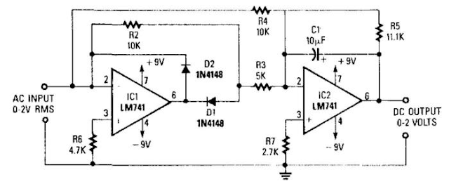
Precision Full Wave Ac Dc Converter Circuit Diagram
A dc level is produced that corresponds to the ac input rms value (if sine wave), -i set the gain of IC2 to 1.11. This factor is the average-to-rms conversion factor. IC1 and IC2 act as a full-wave rectifier circuit, with Dl and D2.
Precision Full-Wave Ac/Dc Converter Circuit Diagram
Monday, 26 December 2016
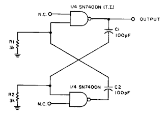
2MHz Square Wave generator Circuit Diagram
With the values shown the circuit generates a 2-MHz symmetrical square wave. Changing capacitors Cl and C2 to 0.01 µ¥ results in a frequency of 500 Hz. For the particular integrated circuits and power supply voltages (5.0 V), the reliable operating range of Rl = R2 is 2 k ohm to 4 k ohm.
2MHz Square Wave generator Circuit Diagram
Saturday, 19 November 2016
Wave antenna 5 8 pro VKV FM
Wave antenna 5/8 consists of a vertical radiator which is fed at the base of the antenna. A suitable device of some sort should be added between the antenna and feedline if you want to eat with coax. Adding a coil in series with the antenna on the base is one of these methods are suitable.


So why would anyone use an antenna 5/8 wave if they have to go through all that extra work? After all, a ground plane antenna provides a good match. There are several answers. The first is GAIN. The computer shows that the antenna (mounted 1 foot above the ground) has a margin of about 1.5 dBd higher than a dipole (also installed 1 foot above the ground.)The second reason you might want to use the wave 5/8 vertical is to get a lower angle of radiation. Peak radiation angle A half-wave antenna is 20 degrees. You will find that the angle 5/8 wave antenna radiation is only 16 degrees so it is better dx antenna.
You may have noticed a pattern developing here. A quarter-wave ground plane antenna has a radiation pattern that produces the maximum gain at about 25 degrees and half-wave antenna drops to 20-degree angle, and wave antenna 5/8 further drops to 16 degrees angle. So why not just keep extending the antenna to one full wave? Well it would be nice if it worked, but unfortunately the wave patterns begin to create a very high angle of radiation waves exceed 5/8. So we've reached the maximum gain at this point and extend the antenna further reduce profits only where we want it (low angle).
Of course if you are interested in a very short jump, extend the antenna will produce a nice profit on the dipole.All the length of the antenna depends on various factors. Some of these factors are: height above ground, the diameter of the wire, nearby structures, the effects of other antennas in the area and even the conductivity of the soil.This page allows you to calculate the wavelength for the antenna 5/8. It uses the standard formula, 585 / f (178.308 / f for metric) MHz to calculate the length of the element. If you have experimented with 5/8 wave antenna before and know a better formula for your QTH, feel free to change the formula accordingly. This formula is for the antenna wire.
Of course if you build your antenna out of the tube, total length of the antenna will be shorter, for example I have found that 21.5 feet seems to provide maximum benefit to the frequency of 28.5 MHz when using a 1 "tube, and 22.5. Foot seems be the best long-wire at the same frequency. Since the formula to calculate the antenna to be about 2 feet shorter, be sure to experiment and maybe add a little for your final term.
Friday, 11 November 2016
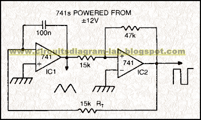
Simple Triangle Square wave Oscillator Circuit Diagram
Simple triangle-square wave oscillator circuit diagram. In this circuit by making Rt variable it is possible to alter the operating frequency over a 100 to 1 range Versatile triangle/square wave oscillator has a possible frequency range of 0 Hz to 100 kHz.
Triangle Square wave Oscillator Circuit Diagram
Sourced By: circuitsdiagram-lab
Monday, 7 November 2016
Inverter Voltage Wave Circuit Diagram
This circuit voltage inverter was designed using common electronic components, it produces a negative voltage from a positive. It is very simple, its operation is reasonable and can be used in different utilities in electronics where one has to inverts tensions of a wave.
Inverter Voltage Wave Circuit Diagram

Subscribe to:
Posts (Atom)