Showing posts with label DC. Show all posts

Friday, 24 March 2017

LTM4620 – Dual 13A or Single 26A DC DC µModule Regulator with Integrated Heatsink


The LTM4620 is a dual 13A per output (or single 26A output) DC/DC μModule step-down regulator that delivers up to 100A when four devices are current shared. The LTM4620 is a complete DC/DC regulator system in a 15mm x 15mm x 4.41mm LGA package, including inductors, power stages and all control circuits. For optimum heat dissipation, an integrated top side heat sink removes heat quickly and evenly.


Readmore → LTM4620 – Dual 13A or Single 26A DC DC µModule Regulator with Integrated Heatsink

Friday, 3 March 2017

Simle DC to AC Inverter by IC 555


This be basic AC inverter Circuit. Convenient for the initiator who have to is extremely fond of something experience. Because of use IC 555 highly popular, perform produce the frequency ,then enlarge with transistor NPN and PNP number TIP41 and TIP42 drive the coil transformer. Get by can pay Voltage output about 120V to 230V at frequency 50Hz. By have R4 perform control the frequency and should use. Voltage supply about 5V to 15V the detail sees in circuit picture sir.

Simple DC to AC Inverter by IC 555 Circuit Diagram


Readmore → Simle DC to AC Inverter by IC 555

Thursday, 2 February 2017

TDA7275A DC Speed Controller


Using the TDA7275A linear integrated circuit manufactured in a minidip plastic package can be designed a very simple speed regulator electronic project that can be used for speed regulation of small DC motors .


TDA7275A DC Speed Controller Schematic


TDA7275A DC speed controller project is intended for use as speed regulator for DC motors of record players, tape and cassette recorders. This DC motor speed controller circuit project can provide a maximum output current of 1.5 amperes .

This circuit can be powered with a voltage range between 8 and 18 volts . V2 is typically 1.5 volt for Motor ”Run” (Acc. Following data or open) and 1 volt for Motor ”Stop” (Acc. Following data or grounded) .

Readmore → TDA7275A DC Speed Controller

Sunday, 22 January 2017

zBot 10 A Power Stage for DC Motor Circuit Diagram


zBot :10-A Power Stage for DC Motor Circuit Diagram . If you look at the chassis of the zBot vehicle1, you’ll find two parts requiring intelligent control: the steering servo and the DC motor. The so called H-bridge is the normal circuit for electronic control of revolution speed and direction. The DC motor of a Tamiya car is powerful enough to propel zBot at up to 20 miles per hour.
.
The motor then consumes more than 10 A, so we choose high-current power MOSFETs for the driver stage. There are lots of different devices to choose from. The MOSFET we require has to supply the maximum motor current and, importantly, it has to be switched with gate voltages of about 5 V. In this case, the microcontroller switches the power stage (‘low side’) directly. For high side driving level shifters are necessary. The schematic of the H-bridge power stage shows a few inverters, NAND gates and two tri-stateable drivers. These logic functions are very important as the easier way, i.e.., directly controlling all four MOSFET has a fatal disadvantage.

zBot :10-A Power Stage for DC Motor Circuit Diagram

zBot :10-A Power Stage for DC Motor Circuit Diagram


In case of a software crash it could happen that two ore more MOSFETs are switched on incor-rectly for exam-ple, T4 and T7. In that case, the current through the transistors is limited by the internal resistors of the MOSFETs (about 10 mO) only. Such a fatal error would destroy the MOSFETs. The logic functions configured here effectively avoid illegal states.To control the DC motor, three signals are needed: DIR, PWM and STOP. DIR controls the direction of the motor revolution, PWM the speed, and STOP brakes the motor.

The software module for the DC motor is called dcm.c.(070172-I) The complete document called Zbot  the Robot Experimental Platform is available for free downloading from the Elektor Electronics website. The file number is 070172-11.zip (July/August 2007).

Sourced by : Circuitsstream.blogspot.com

Readmore → zBot 10 A Power Stage for DC Motor Circuit Diagram

Saturday, 21 January 2017

LT3582 12 DC 5V to 12V DC Converter Circuit Diagram


Using LT3582-12 dual channel DC DC converter integrated circuit, manufactured by Linear Technology, can be designed a very simple step up dc converter. This 5 to 12V c converter electronic project provide both positive and negative outputs required in many biasing applications such as active matrix OLED (organic light-emitting diode)displays as well as CCD (charge coupled device) applications.

LT3582-12 DC 5V to 12V DC Converter Circuit Diagram


LT3582-12 DC 5V to 12V DC Converter Circuit Diagram


Readmore → LT3582 12 DC 5V to 12V DC Converter Circuit Diagram

Friday, 20 January 2017

Variable DC Power Supply Rise Circuit Diagram


This Variable DC Power Supply (Rise) Circuit Diagram project provides the schematic & the parts list needed to construct a simple DC Power Supply from an input power supply of 7-20 V AC or 7-30V DC. This project will come in handy in case you use plenty of batteries for your basic electronics project.

Two DC voltage outputs are available; is a fixed regulated 5V for TTL use. The other output is variable from 5V upwards. The maximum output voltage depends on the input voltage. The specified maximum input DC voltage to the regulator is 35V. The maximum input voltage must be two volts higher than the regulated output voltage.

 Variable DC Power Supply (Rise) Circuit Diagram
Variable DC Power Supply Circuit Diagram


The DC Power Supply circuit is based around the 7805 voltage regulator. It's only three connections input, output & ground & it provides a fixed output. The last digits of the part number specify the output voltage, e g. 05, 06, 08, ten, 12,15, 18, or 24. The 7800 series provides up to one amp load current & has on-chip circuitry to close down the regulator if any attempt is made to operate it outside its safe operating area.It can be seen that there's in fact separate circuits in this power supply. 7805 is directly connected as a fixed 5V regulator. The second 7805 has a resistor divider network on the output. A variable 500 ohm potentiometer is used to vary the output voltage from a maximum of 5V up to the maximum DC voltage depending on the input voltage. It will be about 2V below the input DC voltage.

The capacitor across the output improves transient response. The giant capacitor across the input is a filter capacitor to help smooth out ripple in the rectified AC voltage. The larger the filter capacitor the lower the ripple.

For tiny applications the heat sinks won't be needed. The tab on the regulator will dissipate 2W at 25 o C in air. (This is equivalent, for example, to an input voltage of 9V, an output of 5V & drawing 500 m A.) However, as your projects get bigger they will draw more current from the power supply and the regulators will operate at a higher temperature and a heat sink will be needed. You can basically add voltage & current meters to it and put it in to an appropriate plastic case connected to a transformer.

Trouble Shooting Procedure

An LED has been put in to the output of the fixed 5V regulator to indicate that the circuit is working. Poor soldering is the most likely reason that the circuit does not work. Check that all the soldering is done properly. Check that all parts are in their correct position on the PCB. Other items to check are to make sure that the regulators, electrolytic capacitor & bridge rectifier are inserted in the correct orientation.

Readmore → Variable DC Power Supply Rise Circuit Diagram

Saturday, 14 January 2017

H bridge Control the Direction of Rotation for DC motor Circuit Diagram


This circuit can control the direction of a DC motor., It has many applications that are necessary to operate a motor in both directions, clockwise and counter-clockwise (forward and backward). One way to accomplish this is to start the engine in a circuit arrangement of transistors called H-bridge. H bridge is an electronic circuit which enables a voltage is applied across a load in either direction. This circuit is often used in robotics and other applications to allow DC motors to become bi-directional.

H-bridge Control the Direction of Rotation for DC motor Circuit Diagram

H-bridge Control the Direction of Rotation for DC motor Circuit Diagram


List of components

PARTS LIST
R1, R2, R3, R4 220Ω
R5, R6, R7, 1K Ohm
D1, D2, D3, D4 1N4001
D5, D6 LED
Q1, Q2 2SD313
Q3, Q4 2SB507
PB1, PB2 switch
M1 12V DC MOTOR

In this circuit usually PB1 and PB2 are open. Thus, the bases of the transistors are grounded. Hence Q3 and Q4 are turned on, Q1 and Q2 are turned off. The voltages at both terminals of the motor is the same and thus the engine is switched off. Similarly, when both PB1 and PB2 are "on" motor is turned off. The LEDs indicate the direction of motor rotation.

Readmore → H bridge Control the Direction of Rotation for DC motor Circuit Diagram

DC Motor Speed Controller


This is the schematic diagram of DC motor speed controller circuit. The circuit applies two oscillators/timers which are connected as a Pulse Width Modulator (PWM). The timer chip which applied in this circuit will be an nmos dual timer/oscillator NE556. This timer IC has two 555 timers in a single 14-pin IC package.

One 555 (IC1:B) is set up as an astable oscillator. The output frequency of the trigger pulses is specified by:
f = 1.44 / ((R3 + 2R4)C2), or about 410Hz.
The time period for the high output is specified by
THIGH = 0.69(R3 + R4)C2 seconds.
And, the low output by TLOW = 0.69R4C2 seconds. The 2nd 555 (IC1:A) is set up for Pulse Width Modulation. It will be build in monostable mode. It is triggered using the continuous pulse train from the first 555 timer. Nevertheless, by also applying a DC voltage to pin 3, the comparator reference levels are going to be modified from their nominal levels of one-third & two-thirds of the supply voltage. This has the effect of modulating the pulse width as the control voltage varies. The control voltage is supplied via transistor Q1, which is configured as an emitter-follower. This means that the emitter output voltage follows the base input voltage (less 0.6 volt base-emitter drop). This configuration gives us a low output impedance voltage source with which to drive the control input of the timer. This makes the control voltage less susceptible to the loading effect of the timer control input.
The output from the timer is a continuous stream of pulses whose width is controlled by the voltage level used on the control voltage input. This modulated output drives a MOSFET, Q2, that is applied to switch the voltage to the DC motor.
Components List:
R1 = 560R
R2 = 470R
R3 = 33K
R4, R7 = 2K2
R5 = 10K
R6 = 10R
P1 = 500R (501) Koa trimpot
RV1 = 10K potentiometer
D1 = 1N4004
C1 = 10uF/50V
C2, C3, C4, C5, C6, C7 = 100nF
C8 = 100uF/25V
IC1 = Nmos LM/NE556
Q2 = IRF530 mosfet
Q1 = BC547 Transistor
Technical Details:
  • Uses NE556 to pulse-width modulate IRF530N MOSFET.
  • DC Motor Speed Controlled via a potentiometer.
  • Speed control for DC motors up to 100 Volts @ 7.0Amps without sacrificing motor torque.
  • This DC Motor controller can handle up to 16 Amps, but PCB trace capacity would have to be beefed up with some hookup wire where DC motor current runs through the Printed Circuit Board.
  • Requires operating voltage of 5 – 16 VDC.


Readmore → DC Motor Speed Controller

Sunday, 1 January 2017

Versatile DC DC Converter Circuit Diagram


Here is a versatile power coupler that connects a device to 5V-19V DC generated from AC mains by a power adaptor. Power adaptors come in different voltage outputs like 5V (for mobile phones), 12V (for external hard drives) and 19V (for laptops). Sometimes the power adaptor may have a voltage rating higher than the required voltage. With the converter circuit given here, the adaptor can be used to power any device at a lower voltage. 

For instance, by using a 19V laptop adaptor, you can power a TTL circuit at 5V. There can also be other instances when one needs a 3V or 6V supply. All these and many other intermediate voltages are easily possible with this versatile converter circuit when used together with any off-hand power adaptor.

Circuit diagram :

Versatile DC-DC Converter-Circuit diagram
Versatile DC-DC Converter Circuit diagram

Fig. 1 shows the circuit of the DC-DC converter. Smooth reduction in the voltage is achieved using the LM317 regulator IC. The complete unit can fit inside a piece of a glue stick tube.
Adjusting variable resistor VR1 gives the desired output voltage. The output voltage is read using a 0-100µA ammeter, whose series resistance R* is chosen such that the maximum desired voltage could be covered. For instance, if full-scale deflection (FSD) current of the meter is 100 µA and you need an output voltage of up to 15V, then R* = 15/0.0001 = 150 kΩ. The desired value of R* is obtained by using 150-kilo-ohm preset VR2. 

Use of a variable resistor which also has an on/off switch like the one in old radios is recommended. It will cut off the coupler from the input power supply without having to accomodate an additional switch. Also, use a heat-sink with LM317 to handle the desired amount of power.

Proposed-assembly

Assemble the circuit on a small general-purpose PCB and enclose in a suitable case. Fit the entire PCB inside a glue stick tube as shown in Fig. 2. Affix the female and male connectors on the opposite ends and place the ammeter in between the stick tube. You can directly read the output voltage on the ammeter after due calibration.

Note. You can use a suitable VU meter instead of 0-100µA ammeter and calibrate accordingly.
Source By Streampowers

Readmore → Versatile DC DC Converter Circuit Diagram

Thursday, 29 December 2016

Precision Full Wave Ac Dc Converter Circuit Diagram


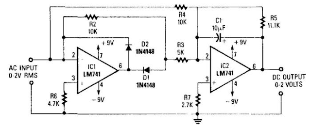
A dc level is produced that corresponds to the ac input rms value (if sine wave), -i set the gain of IC2 to 1.11. This factor is the average-to-rms conversion factor. IC1 and IC2 act as a full-wave rectifier circuit, with Dl and D2. 

Precision Full-Wave Ac/Dc Converter Circuit Diagram


Precision Full-Wave Ac/Dc Converter Circuit Diagram

Readmore → Precision Full Wave Ac Dc Converter Circuit Diagram

Wednesday, 28 December 2016

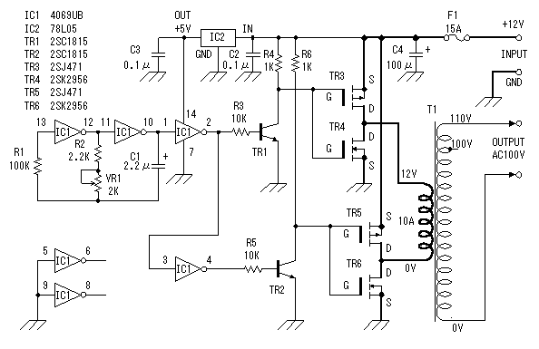
DC to AC converter 12 to 100 Voltage circuit with IC


An AC-DC voltage converter with electrically isolated with onput and output circuits and converters with a transformer with at least one primary coil and a capacitor resonance said coil to at least one primary school.
A switching transistor whose collector-emitter path is connected in series at least a coil and the primary school to the transistor switching system for the storage in the database of the surface sensors.
switching power transistor provides the foundation for the transistor switching system, and by other means in order to increase the voltage transmitter Collector of the transistor switching and deliver a response to such an increase and at least in the period immediately after the increase.
 one while driving for the transistor circuit, the additional base current is very progressive with a predetermined, so that the storage of the relatively constant switching transistor in the beach for the operation of the converter.

Readmore → DC to AC converter 12 to 100 Voltage circuit with IC

Thursday, 15 December 2016

1 5V to 5V 12V DC DC Converter with LT1073


 1.5V to 5V/12V DC/DC Converter with LT1073 Circuit
1.5V to 5V/12V DC/DC Converter with LT1073
Small 1.5V to 5V or 12V DC/DC converter with LT1073 chip. The IC is available in three different versions, depending on output voltage. Two with fixed output voltage of 5V and 12V, and the most interesting that can be adjusted. The adjustment is done through a voltage divider with two resistors, of mass, output and Terminal 8, internally connected to the voltage comparator IC, which is responsible for stabilizing the output voltage. 
 
1.5V to 5V/12V DC/DC Converter with LT1073

Readmore → 1 5V to 5V 12V DC DC Converter with LT1073

Friday, 9 December 2016

HV Nixie DC DC Power Supply


Nixie tubes need about ~180Vdc to light up and thus on most devices a DC-DC converter is needed. We designed here a simple DC-DC switching regulator capable of powering most of Nixie tubes.

HV Nixie DC-DC Power Supply

The module is based on the MAX1771 Step-Up DC-DC Controller. This controller works up to 300kHz switching frequency and that allows the usage of miniature surface mount components. It accepts an input voltage from 2 to 16.5V and the output is factory configured to 12V. In this module the output voltage is configured higher at ~180Vdc using external resistors and a potentiometer.

[ ]
Readmore → HV Nixie DC DC Power Supply

Friday, 2 December 2016

Versatile DC DC Converter Circuit Diagram


Here is a versatile power coupler that connects a device to 5V-19V DC generated from AC mains by a power adaptor. Power adaptors come in different voltage outputs like 5V (for mobile phones), 12V (for external hard drives) and 19V (for laptops). Sometimes the power adaptor may have a voltage rating higher than the required voltage. With the converter circuit given here, the adaptor can be used to power any device at a lower voltage. 

For instance, by using a 19V laptop adaptor, you can power a TTL circuit at 5V. There can also be other instances when one needs a 3V or 6V supply. All these and many other intermediate voltages are easily possible with this versatile converter circuit when used together with any off-hand power adaptor.


Versatile DC-DC Converter-Circuit diagram
Versatile DC-DC Converter Circuit diagram

Fig. 1 shows the circuit of the DC-DC converter. Smooth reduction in the voltage is achieved using the LM317 regulator IC. The complete unit can fit inside a piece of a glue stick tube.
Adjusting variable resistor VR1 gives the desired output voltage. The output voltage is read using a 0-100µA ammeter, whose series resistance R* is chosen such that the maximum desired voltage could be covered. For instance, if full-scale deflection (FSD) current of the meter is 100 µA and you need an output voltage of up to 15V, then R* = 15/0.0001 = 150 kΩ. The desired value of R* is obtained by using 150-kilo-ohm preset VR2. 

Use of a variable resistor which also has an on/off switch like the one in old radios is recommended. It will cut off the coupler from the input power supply without having to accomodate an additional switch. Also, use a heat-sink with LM317 to handle the desired amount of power.

Proposed-assembly

Assemble the circuit on a small general-purpose PCB and enclose in a suitable case. Fit the entire PCB inside a glue stick tube as shown in Fig. 2. Affix the female and male connectors on the opposite ends and place the ammeter in between the stick tube. You can directly read the output voltage on the ammeter after due calibration.

Note. You can use a suitable VU meter instead of 0-100µA ammeter and calibrate accordingly.

Copyright : EFY

Readmore → Versatile DC DC Converter Circuit Diagram

Monday, 21 November 2016

DC to DC Converter Circuit


Discription 
The circuit below is a DC to DC converter using a standard 12 VAC center tapped power transformer wired as a blocking oscillator. The circuit is not very efficient but will produce a high voltage usable for low power applications. The input battery voltage is raised by a factor of 10 across the transformer and further raised by a voltage tripler consisting of three capacitors and diodes connected to the high voltage side of the transformer. The circuit draws about 40 milliamps and should operate for about 200 hours on a couple of 'D' alkaline batteries. Higher voltages can be obtained by reducing the 4.7K bias resistor.
Circuit Diagram
 Source - http://www.bowdenshobbycircuits.info/page4.htm#triple.gif

Readmore → DC to DC Converter Circuit

Tuesday, 1 November 2016

DC to AC Inverter by IC 555 Circuit Diagram


This be basic AC inverter Circuit. Convenient for the initiator who have to is extremely fond of something experience. Because of use IC 555 highly popular, perform produce the frequency ,then enlarge with transistor NPN and PNP number TIP41 and TIP42 drive the coil transformer. Get by can pay Voltage output about 120V to 230V at frequency 50Hz. By have R4 perform control the frequency and should use. Voltage supply about 5V to 15V the detail sees in circuit picture sir.

DC to AC Inverter by IC 555 Circuit Diagram

DC to AC Inverter by IC 555 Circuit Diagram


Readmore → DC to AC Inverter by IC 555 Circuit Diagram