Showing posts with label Supply. Show all posts

Thursday, 23 March 2017

12 Volt 2 A Switching Power Supply Circuit Diagram


This is a Simple 12 Volt / 2 A Switching Power Supply Circuit Diagram. The circuit 12 volt / 2 A switching power supply in the above scheme is not too complicated. At the output of this block provides a stable 12 V and maximum current 2A. Power supply units are quite compact and is suitable for debugging schemes, as well as a permanent resource for stationary devices, including power for the logic electronics for the home-made ​​CNC machine tools. 

Circuit Diagram


12 Volt / 2 A Switching Power Supply Circuit Diagram


Transformer is available in the free market and avoids the hassle of having to self-winding. The diode bridge BR 1 of any given voltage and current of 2A. All other elements in the high part of the circuit are designed by the same voltage, taking into account the mains. The scheme of 12 volt / 2 A switching power supply operates from the high voltage network, to be observed when mounting accuracy and caution when using. It is desirable to block the finished board to “pack” in the body. 
Readmore → 12 Volt 2 A Switching Power Supply Circuit Diagram

Wednesday, 15 March 2017

Adjustable Voltage Current Power Supply Circuit Using IC L200


IC2 is connected as a differential amplifier and compares the signals at its two inputs.
Referring to the circuit diagram: the input comprises a mains switch, fuse, transformer, bridge rectifier and smoothing capacitor (C2). 


The difference between the inputs is the voltage drop across 'current’ sensor R4. This IC feeds the current sensing input (pin 2) of the L200. 


P1 in the feedback loop of the 741 is used to vary the output current of the circuit. IC1 must be mounted on a suitable heat sink as it dissipates nearly all the power of the circuit.
The reference level output from I pin 4 of IC1 goes to the voltage divider made up of R5 and P2 (this pot sets the value of the output voltage).


The power supply can quite easily be built into a case and a voltmeter and ammeter mounted on the front panel. ln view of the accuracy of the circuit these should ideally be digital meters, but virtually any type will do.


If you compare the expense and the rating of this power supply you will get a surprise, because the output voltage and current are fully adjustable between O. . . 18 V and 0 . . . 1.8 A respectively and costs have still been kept very reasonable. 


Diode D5 and capacitor C1 produce a negative auxiliary voltage, which is stabilized by zener diode D6 and capacitor C4. 


All this is necessary to enable the output voltage to be adjusted down to zero volts. During the construction of this part of the circuit bear in mind that the positive lead of electrolytic capacitor C4 is connected to earth! Regulation is provided by IC1 and IC2. Capacitor C3 suppresses any residual transients at the input of lC1 and it should therefore be connected as closely as possible to IC1 similarly C4 and IC2). 


The negative voltage provides the negative supply for the two ICs.


 Adjustable Voltage, Current Power Supply Circuit Using IC L200

Readmore → Adjustable Voltage Current Power Supply Circuit Using IC L200

Friday, 10 March 2017

Low ripple power supply schematic


Simple schematic above is a circuit of power supply that can operate at high current with very small ripple voltage. How it works similiar to the high power class AB amplifiers, with the same quality. T1,T2 ,and R2 can also be called a power NPN-Darlington transistor. ZD1 and R1 as a supplier of voltage on the transistor base and filtered by C2. ZD1 can be slected with formulated (Figure 1.0) . For the C2 can be selected in accordance with the degree of smoothness as its value is effectively combined with the multiplied gain of the Transistor T1 and T2, assumsing minimum hfe for T1 and T2 , C=100x15(T1) x 25 (T2) = 37,000uF, adjust the voltage C2 with the input voltage, but must be higher than input voltage.
Low ripple power suplly regulator
Part List :
R1 = 2K2
R2 = 56R
R3 = 10K
C1 = 1500uF
D1-D4 = Didode 6A
T1 = 2N3054
T2 = 2N3055
rumus tegangan ripple
Figure 1.0

Readmore → Low ripple power supply schematic

Saturday, 4 March 2017

LM338 Power Supply 13 8V 5A


This ac to dc power supply can output 5A in continous operation and 12A peak current. This kind of dc power supplies uses a PCB so you can use two case types for IC1, TO-220 or TO-3. The regulation of this 12 volt power supply is made with TR1 ( multiturn ). IC1 must be placed on proper heatsink.

LM338 Power Supply Circuit Diagram :


 13.8V 5A power sp-Circuit Diagram

Readmore → LM338 Power Supply 13 8V 5A

Tuesday, 31 January 2017

Power Supply for Walkie Talkies


Power Supply for Walkie-Talkies
Here is a simple power supply circuit that can be used for citizen-band and VHF walkie-talkies of power rating up to 10 watts. The circuit uses a step-down transformer, followed by bridge rectifier, filter, regulator, and current booster stages.
A pnp power transistor is added to the circuit to increase its current sourcing capabilities. Regulator 7812 can support
around 100 mA current. When the current
flowing through R1 nears 100mA value, the  voltage (>0.65V) across the emitter-base junction makes transistor T1 to conduct and provide a path for additional current. The circuit can source around one ampere of current at 12+1.4 volts=13.4 volts. Both the regulator IC and the power transistor must be mounted on heat sinks.

Readmore → Power Supply for Walkie Talkies

Friday, 20 January 2017

Variable DC Power Supply Rise Circuit Diagram


This Variable DC Power Supply (Rise) Circuit Diagram project provides the schematic & the parts list needed to construct a simple DC Power Supply from an input power supply of 7-20 V AC or 7-30V DC. This project will come in handy in case you use plenty of batteries for your basic electronics project.

Two DC voltage outputs are available; is a fixed regulated 5V for TTL use. The other output is variable from 5V upwards. The maximum output voltage depends on the input voltage. The specified maximum input DC voltage to the regulator is 35V. The maximum input voltage must be two volts higher than the regulated output voltage.

 Variable DC Power Supply (Rise) Circuit Diagram
Variable DC Power Supply Circuit Diagram


The DC Power Supply circuit is based around the 7805 voltage regulator. It's only three connections input, output & ground & it provides a fixed output. The last digits of the part number specify the output voltage, e g. 05, 06, 08, ten, 12,15, 18, or 24. The 7800 series provides up to one amp load current & has on-chip circuitry to close down the regulator if any attempt is made to operate it outside its safe operating area.It can be seen that there's in fact separate circuits in this power supply. 7805 is directly connected as a fixed 5V regulator. The second 7805 has a resistor divider network on the output. A variable 500 ohm potentiometer is used to vary the output voltage from a maximum of 5V up to the maximum DC voltage depending on the input voltage. It will be about 2V below the input DC voltage.

The capacitor across the output improves transient response. The giant capacitor across the input is a filter capacitor to help smooth out ripple in the rectified AC voltage. The larger the filter capacitor the lower the ripple.

For tiny applications the heat sinks won't be needed. The tab on the regulator will dissipate 2W at 25 o C in air. (This is equivalent, for example, to an input voltage of 9V, an output of 5V & drawing 500 m A.) However, as your projects get bigger they will draw more current from the power supply and the regulators will operate at a higher temperature and a heat sink will be needed. You can basically add voltage & current meters to it and put it in to an appropriate plastic case connected to a transformer.

Trouble Shooting Procedure

An LED has been put in to the output of the fixed 5V regulator to indicate that the circuit is working. Poor soldering is the most likely reason that the circuit does not work. Check that all the soldering is done properly. Check that all parts are in their correct position on the PCB. Other items to check are to make sure that the regulators, electrolytic capacitor & bridge rectifier are inserted in the correct orientation.

Readmore → Variable DC Power Supply Rise Circuit Diagram

Sunday, 1 January 2017

Power Supply for Walkie Talkies Circuit Diagram


Power supply circuit that can be used for citizenband and VHF walkie-talkies of power rating up to 10 watts. The circuit uses a step-down transformer, followed by bridge rectifier, filter, regulator, and current booster stages. A pnp power transistor is added to the circuit to increase its current sourcing capabilities. Regulator 7812 can support around 100 mA current. When the current flowing through R1 nears 100mA value, the voltage (>0.65V) across the emitter-base junction makes transistor T1 to conduct and provide a path for additional current.

Circuit diagram :

Power Supply for Walkie Talkies Circuit Diagram


Power Supply for Walkie Talkies Circuit Diagram
The circuit can source around one ampere of current at 12+1.4 volts=13.4 volts. Both the regulator IC and the power transistor must be mounted on heat sinks.


Readmore → Power Supply for Walkie Talkies Circuit Diagram

Wednesday, 28 December 2016

Pre regulated High Voltage Power Supply


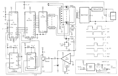
This Pre-regulated High Voltage Power Supply Circuit Diagram triacs selects the tap on main transformer Tl, which provides the proper, pre-regulated voltage to the secondary regulator. T2 and its associated components comprise the secondary regulator. The ADC 0804, IC1, digitizes a voltage-feedback signal from the secondary regulator`s output.

Pre-regulated High Voltage Power Supply Circuit Diagram:

 Power-Supply

The MC1415 De-multiplexer, IC2, decodes the digitizer`s output. IC2, in turn, drives Tl`s opto-isolated triacs via the 74LS240 driver chip, IC3, and associated opto-isolators. Transformer T3 samples the circuit`s current output. The auxiliary, 12 V winding on Tl ensures noload starting. The combination of op amp IC5 and the inverting transistor, Ql, square this current signal.

The output of Ql is the CLK signal, which triggers one-half of the one shot, IC4A, to begin the circuit`s AID conversion. The one shots` periods are set to time out within 1l2 cycle of the ac input. Upon completion of its AID conversion, ICl`s INTR output triggers the other half of the one shot, IC4B, which enables the converter`s data outputs. The rising edge of the CLK signal resets the one shot and latches the new conversion value into IC2. The latch, associated driver, and optoisolator trigger a selected triac according to the latest value of the voltage-feedback signal, V, . Keep enjoying don't forget click on share button .

Readmore → Pre regulated High Voltage Power Supply

Friday, 16 December 2016

Simple 2 Watt Small Switching Power Supply Circuit Diagram


In this small switching power supply, a Schmitt trigger oscillator is used to drive a switching transistor that supplies current to a small inductor. Energy is stored in the inductor while the transistor is on, and released into the load circuit when the transistor switches off.

2 Watt Small Switching Power Supply Circuit Diagram

Simple 2 Watt Small Switching Power Supply Circuit Diagram

The output voltage is dependent on the load resistance and is limited by a zener diode that stops the oscillator when the voltage reaches about 14 volts. Higher or lower voltages can be obtained by adjusting the voltage divider that feeds the zener diode. The efficiency is about 80% using a high Q inductor.

Readmore → Simple 2 Watt Small Switching Power Supply Circuit Diagram

Saturday, 10 December 2016

Dual Power Supply Circuits


This is a bench top power supply that can be used to power circuits or devices during development work in the lab. More specifically it is an adjustable, tracking, dual rail supply which means there are two supply voltages, one positive, one negative, that are adjusted by a common potentiometer such that supply voltages are equal in magnitude. It is capable of supplying up to +/- 15V DC at up to 1A. This is sufficient for the majority of small signal electronic projects.

Dual Power Suplly Circuit diagram.
Dual Power Supply Circuits
Click to view larger


Power Supply circuit above shows the circuit layout for this project. A centre tapped transformer (TR1) is used with two 12V secondary windings with its centre tap tied to ground. This allows positive and negative voltages to be generated with respect to the central ground. Rectification follows based upon the bridge rectifier (BR1) and smoothing capacitors (C1, C2, C4 and C5).

Two linear regulators are used, an LM317 on the positive side and an LM337 on the negative side. These regulators keep the supply voltage constant for a varying load up to a load current of around 1A. The voltage adjustment is achieved through potentiometers RV1 and RV2 in the positive side of the circuit. The clever part of this circuit comes from the mirroring of the positive voltage adjustment to the negative side via the op-amp U2 to give the circuit its tracking nature.

The op-amp U2 has its positive input tied to ground via a 4K7 resistor. This means that, providing there is negative feedback around the op-amp, the op-amp will endeavour to make its negative input also at ground or 0V. The negative feedback is arranged by the output of the op-amp U2 driving the Adjust pin of the negative regulator U3 and by resistors R3 and R4. The op-amp U2 sets the voltage on the adjust pin of U3 such that the voltage at its negative input is 0V. Also as R3 and R4 are equal, the positive and negative regulated voltages must then be equal in magnitude.

An analogue meter is driven from the positive side to give an indication of the voltage setting. Two switches are used to allow the positive and negative supplies to be turned on/off independently and there are also two LED acting as indicators.

Dual Power Supply Construction

This power supply circuit was built up on Veroboard as it is quite simple to build. Heatsinks can be mounted to the two regulators to improve the current drive capability. The transformer and circuit were mounted inside a wooden box. If a metal box is used the box must be connected to mains earth to prevent a shock hazard. Figure 2 shows a picture of the finished unit. It should be noted that this box is rather shabby and the author has been meaning to improve it for a while but it does do the job nicely.

Readmore → Dual Power Supply Circuits

Friday, 9 December 2016

HV Nixie DC DC Power Supply


Nixie tubes need about ~180Vdc to light up and thus on most devices a DC-DC converter is needed. We designed here a simple DC-DC switching regulator capable of powering most of Nixie tubes.

HV Nixie DC-DC Power Supply

The module is based on the MAX1771 Step-Up DC-DC Controller. This controller works up to 300kHz switching frequency and that allows the usage of miniature surface mount components. It accepts an input voltage from 2 to 16.5V and the output is factory configured to 12V. In this module the output voltage is configured higher at ~180Vdc using external resistors and a potentiometer.

[ ]
Readmore → HV Nixie DC DC Power Supply

0 30V Stabilized Variable Power Supply with Current Control


0-30VDC variable power supply circuit


This is high quality stabilized power supply circuit diagram. You will able to adjust the output voltage from 0 volt up to 30 volt DC. You also able to adjust the current output value from 0.002 A to 3 A. This variable power supply incorporates an electronic output current limiter that effectively controls the output current from a few mA (2 mA) to the maximum output of 3 A that the circuit can produce.

Component list:
R1 = 2,2 KOhm 1W
R2 = 82 Ohm 1/4W
R3 = 220 Ohm 1/4W
R4 = 4,7 KOhm 1/4W
R5, R6, R13, R20, R21 = 10 KOhm 1/4W
R7 = 0,47 Ohm 5W
R8, R11 = 27 KOhm 1/4W
R9, R19 = 2,2 KOhm 1/4W
R10 = 270 KOhm 1/4W
R12, R18 = 56KOhm 1/4W
R14 = 1,5 KOhm 1/4W
R15, R16 = 1 KOhm 1/4W
R17 = 33 Ohm 1/4W
R22 = 3,9 KOhm 1/4W
RV1 = 100K trimmer
P1, P2 = 10KOhm linear pontesiometer
C1 = 3300 uF/50V electrolytic
C2, C3 = 47uF/50V electrolytic
C4 = 100nF polyester
C5 = 200nF polyester
C6 = 100pF ceramic
C7 = 10uF/50V electrolytic
C8 = 330pF ceramic
C9 = 100pF ceramic
D1, D2, D3, D4 = 1N5402,3,4 diode 2A – RAX GI837U
D5, D6 = 1N4148
D7, D8 = 5,6V Zener
D9, D10 = 1N4148
D11 = 1N4001 diode 1A
Q1 = BC548, NPN transistor or BC547
Q2 = 2N2219 NPN transistor
Q3 = BC557, PNP transistor or BC327
Q4 = 2N3055 NPN power transistor
U1, U2, U3 = TL081, operational amplifier
D12 = LED diode


Readmore → 0 30V Stabilized Variable Power Supply with Current Control

Wednesday, 7 December 2016

How to Repairing Switching Power Supply


Up to date power supply are renowned as "switching controller power supply." In most swapping supply, the 110 volt AC input is first rectified by two diodes and filtered by a pair of capacitors. This conceives two high- voltage causes; one positive and the other negative. A pair of transistors is then utilized to switch these high voltage supply over the primary winding of a transformer. 

This switching activity is very fast. A usual switching pace is around 40,000 circuits per second or 40KHz. An integrated circuit is commonly utilised to control the transistors. This IC not only controls the pace at which the transistors are swapped, but furthermore controls the amount of time that each transistor is energized. The yield voltage of the power supply is very resolute by the "on" time of the transistors. If the transistors are hold on for a longer time span of time, the output voltage of the provide will rise, while shorter times smaller the yield voltage. This is renowned as "pulse-width modulation." 

 Power Supply

How to Repairing Switching Power Supply


Readmore → How to Repairing Switching Power Supply

Sunday, 4 December 2016

0 30V Stabilized Variable Power Supply with Current Control


0-30VDC variable power supply circuit


This is high quality stabilized power supply circuit diagram. You will able to adjust the output voltage from 0 volt up to 30 volt DC. You also able to adjust the current output value from 0.002 A to 3 A. This variable power supply incorporates an electronic output current limiter that effectively controls the output current from a few mA (2 mA) to the maximum output of 3 A that the circuit can produce.

Component list:
R1 = 2,2 KOhm 1W
R2 = 82 Ohm 1/4W
R3 = 220 Ohm 1/4W
R4 = 4,7 KOhm 1/4W
R5, R6, R13, R20, R21 = 10 KOhm 1/4W
R7 = 0,47 Ohm 5W
R8, R11 = 27 KOhm 1/4W
R9, R19 = 2,2 KOhm 1/4W
R10 = 270 KOhm 1/4W
R12, R18 = 56KOhm 1/4W
R14 = 1,5 KOhm 1/4W
R15, R16 = 1 KOhm 1/4W
R17 = 33 Ohm 1/4W
R22 = 3,9 KOhm 1/4W
RV1 = 100K trimmer
P1, P2 = 10KOhm linear pontesiometer
C1 = 3300 uF/50V electrolytic
C2, C3 = 47uF/50V electrolytic
C4 = 100nF polyester
C5 = 200nF polyester
C6 = 100pF ceramic
C7 = 10uF/50V electrolytic
C8 = 330pF ceramic
C9 = 100pF ceramic
D1, D2, D3, D4 = 1N5402,3,4 diode 2A – RAX GI837U
D5, D6 = 1N4148
D7, D8 = 5,6V Zener
D9, D10 = 1N4148
D11 = 1N4001 diode 1A
Q1 = BC548, NPN transistor or BC547
Q2 = 2N2219 NPN transistor
Q3 = BC557, PNP transistor or BC327
Q4 = 2N3055 NPN power transistor
U1, U2, U3 = TL081, operational amplifier
D12 = LED diode


Readmore → 0 30V Stabilized Variable Power Supply with Current Control

Build a 10 Amp 13 8 Volt Power Supply Circuit Diagram


Sometimes amateurs like to home-brew their power supplies instead of purchasing one off the shelf at any of the major ham radio retail dealers. The advantage to rolling your own power supply is that it teaches us how they work and makes it easier to troubleshoot and repair other power supply units in the shack. It should be noted that there is no real cost advantage to building your own power supply unless you can get a large power transformer and heat sink for a super low price. 

Of course rolling our own gives us the ability to customize the circuit and make it even more reliable than commercial units. The circuit in Figure 1 will give us 10 amps (12 amps surge) with performance that equals or exceeds any commercial unit. The circuit even has a current limiting feature which is a more reliable system than most commercial units have. Just like other commercial units, this circuit uses the LM723 IC which gives us excellent voltage regulation. The circuit uses 3 pass transistors which must be heat sinked. Resistor R9 allows the fine tuning of the voltage to exactly 13.8 volts and the resistor network formed by resistors R4 through R7 controls the current limiting. 

The LM723 limits the current when the voltage drop across R5 approaches .7 volts. To reduce costs, most commercial units rely on the HFE of the pass transistors to determine the current limiting. The fault in that system is that the HFE of the pass transistors actually increases when the transistors heat up and risks a thermal runaway condition causing a possible failure of the pass transistors. Because this circuit samples the collector current of the pass transistors, thermal runaway is not a problem in this circuit making it a much more reliable power supply. 

The only adjustment required is setting R9 to the desired output voltage of anywhere between 10 and 14 volts. You may use a front panel mounted 1K potentiometer for this purpose if desired. Resistor R1 only enhances temperature stability and can be eliminated if desired by connecting pins 5 and 6 of IC-1 together. Although it really isn’t needed due to the type of current limiting circuit used, over voltage protection can be added to the circuit by connecting the circuit of Figure 2 to Vout. The only way over voltage could occur is if transistors Q2 or Q3 were to fail with a collector to emitter short. Although collector to emitter shorts do happen, it is more much more likely that the transistors will open up when they fail.

 10 Amp 13.8 Volt Power Supply Circuit Diagram

10 Amp 13.8 Volt Power Supply Circuit Diagram


I actually tested this and purposely destroyed several 2N3055’s by shorting the emitters to ground. In all cases the transistors opened up and no collector to emitter short occurred in any transistor. In any event, the optional circuit in Figure 2 will give you that extra peace of mind when a very expensive radio is used with the power supply. The circuit in Figure 2 senses when the voltage exceeds 15 volts and causes the zener diode to conduct. When the zener diode conducts, the gate of the SCR is turned on and causes the SCR to short which blows the 15 amp fuse and shuts off the output voltage. 

A 2N6399 (Tech America) was used for the SCR in the prototype but any suitable SCR can be used. While over voltage protection is a good idea, it should not be considered a substitute for large heat sinks. I personally feel the best protection from over voltage is the use of large heat sinks and a reliable current limiting circuit. Be sure to use large heat sinks along with heat sink grease for the 2N3055 transistors. I have used this power supply in my shack for several months on all kinds of transceivers from HF, VHF to UHF with excellent results and absolutely no hum. This power supply will be a welcome addition to your shack and will greatly enhance your knowledge of power supplies.

10 Amp 13.8 Volt Power Supply Circuit Diagram2


Parts
R1 1.5K ¼ Watt Resistor (optional, tie pins 6 & 5 of IC1 together if not used.)
R2,R3 0.1 Ohm 10 Watt Resistor (Tech America 900-1002)
R4 270 Ohm ¼ Watt Resistor
R5 680 Ohm ¼ Watt Resistor
R6,R7 0.15 Ohm 10 Watt Resistor (Tech America 900-1006)
R8 2.7K ¼ Watt Resistor
R9 1K Trimmer Potentiometer (RS271-280)
R10 3.3K ¼ Watt Resistor
C1,C2,C3,C4 4700 Microfarad Electrolytic Capacitor 35 Volt (observe polarity)
C5 100 Picofarad Ceramic Disk Capacitor
C6 1000 Microfarad Electrolytic Capacitor 25 Volt (observe polarity)
IC1 LM723 (RS276-1740) Voltage Regulator IC. Socket is recommended.
Q1 TIP3055T (RS276-2020) NPN Transistor (TO-220 Heat Sink Required)
Q2,Q3 2N3055 (RS276-2041) NPN Transistor (Large TO-3 Heat Sink Required)
S1 Any SPST Toggle Switch
F1 3 Amp Fast Blow Fuse
D1-D4 Full Wave Bridge Rectifier (RS276-1185)
T1 18 Volt, 10 Amp Transformer Hammond #165S18 (Tech America 900-5825)

Readmore → Build a 10 Amp 13 8 Volt Power Supply Circuit Diagram

Tuesday, 15 November 2016

Supply Variable 1V to 9V Circuit using Power PC


This is a variable power supply which converts an input voltage from 12V SMPS / PSU a desktop computer, to an output voltage from 1.25 to 9 volts. This converter will be very useful for electronics hobbyists. 

The circuit uses a LM317T regulator IC that can reach up to 1 ampere, the diode D1 protects against polarity reversal and the diode D2 keeps the output voltage from the input voltage increases when an inductive or capacitive load is connected to the output.Similarly, the capacitor C3 removes any residual noise of the line regulates the voltage potentiometer VR1.


Supply Variable 1V to 9V  using Power PC Circuit Diagram

Supply Variable 1V to 9V Circuit using Power PC


Readmore → Supply Variable 1V to 9V Circuit using Power PC

Adjustable Symmetric 1 to 24VDC 1A Power Supply


                                     Adjustable Symmetric Power Supply Schematic Diagram
This is the circuit diagram of adjustable symmetric 1 to 24VDC, 1A Power Supply. This power supply give dual output positive and negatif output, you can adjust both positif and negative output (+1 to +24VDC and -1 to -24VDC). This kind of power supply also known as dual polarity power supply or splitted power supply which give positive anf negatif output.

This power supply can be used for universal usage, which required not more than 1A DC current. Please take a note that you should adjust the output voltage using general multimeter or DC voltmeter before use this power supply to protect the supplied devices.
Circuit Features:
  • Low cost universal symmetric power supply
  • Just add a suitable transformer and a heatsink
  • Ideal for e.g. op-amp applications, amplifiers, …
  • Trimmers can be replaced by potmeters to allow continuous adjustment of output voltage
  • LED output indicators
Circuit Specifications:
  • Positive and negative output adjustable between 1.2 and 24VDC
  • Output current: up to 2 x 1A continuous (with suitable heatsink)
  • Max. input voltage: 2 x 24VAC
  • Very good line and load regulation
  • Low ripple
  • Short circuit protection
  • Thermal protection


Readmore → Adjustable Symmetric 1 to 24VDC 1A Power Supply

Tuesday, 8 November 2016

3 Rail Power supply Circuit Diagram


This 3- Rail Power supply Circuit Diagram generates three supply voltages using a minimum of components. Diodes D2 and D3 perform full-wave rectification, alternately charging capacitor C2 on both halves of the ac cycle. On the other hand, diode D1 with capacitor C1, and diode D4 with capacitor C3 each perform half-wave rectification.


The full-and half-wave rectification arrangement is satisfactory for modest supply currents drawn from -5 and +12-V regulators IC3 and IC2. You can use this circuit as an auxiliary supply in an up-based instrument, for example, and avoid the less attractive alternatives of buying a custom-wound transformer, building a more complex supply, or using a secondary winding, say 18 Vac, and wasting power in the 5-V regulators. 


Circuit Diagram:


3- Rail Power supply Circuit Diagram
 
Readmore → 3 Rail Power supply Circuit Diagram

Wednesday, 2 November 2016

Power Supply with regulation


power supply universalElectronic devices should be powered by direct current supply of DC (direct current) which is stable in order to work properly. The battery or batteries are the source DC power supply is best. However, for applications that require power supplies larger, the source of the battery is not enough.
A major source of power supply is alternating source of AC (alternating current) from power plants. For that needed a power supply device that can convert AC current into DC. In this article presented the principles of the power supply circuit (power supply), linear start from the simplest rectifier circuit to the power supply was regulation.

Power supply is functioning electronic circuit to supply power to other components in perangakat electronics. All electronic components that exist in an electronic device will receive power supply from the power supply. Power supply is very has a very important role in an electronic device. Therefore, without power supply, an electronic device will not work. The common voltage supplied by the power supply is +5 V, +12 V,-5V,-12V.
Large output voltage of power supply also must we adjust the voltage needs 'burden' or our electronic devices. Because, an electronic device will be able to work well if the supply voltage and power to him just like the specifications of these electronic components. (specification can be seen in the datasheet of a component).
simple power supply schematic

Power supply circuit drawing examples above we can replace with our needs. Pictured above is a simple power supply circuit having 78XX LM as a regulator. Type LM 78XX can we replace it according to our needs. If for example we want the output from the power supply is +12 Volts, then we have to change it into LM7812 LM. And also of course we have to input voltage of +12 volt transformer.

Similarly, if we want a voltage of +5 volts. So we have to replace the LM7805 LM 78XX, and the input voltage from the transformer 5Volt (transformer).

Readmore → Power Supply with regulation