Showing posts with label Small. Show all posts
Showing posts with label Small. Show all posts
Tuesday, 31 January 2017
Small and Super Inverter
Here is a small and super inverter circuit project. This circuit can be used to power a small strobe or fluorescent lamp. It will generate over 400 VDC from a 12 VDC, 2.5 A power supply or an auto or marine battery. While size, weight, and efficiency are nothing to write home about - in fact, they are quite pitiful - all components are readily available (even from Radio Shack) and construction is very straightforward. No custom coils or transformers are required. If wired correctly, it will work.
Output depends on input voltage. Adjust for your application. With the component values given, it will generate over 400 V from a 12 V supply and charge a 200 uF capacitor to 300 V in under 5 seconds.
Super Inverter Circuit Diagram:

For your less intense applications, a fluorescent lamp can be powered directly from the secondary (without any other components). This works reasonably well with a F13-T5 or F15-T12 bulb (but don't expect super brightness). Q1 does get quite hot so use a good heat sink.
Notes:
WARNING: Output is high voltage and dangerous even without large energy storage capacitor. With one, it can be lethal. Take appropriate precautions.

Output depends on input voltage. Adjust for your application. With the component values given, it will generate over 400 V from a 12 V supply and charge a 200 uF capacitor to 300 V in under 5 seconds.
Super Inverter Circuit Diagram:
For your less intense applications, a fluorescent lamp can be powered directly from the secondary (without any other components). This works reasonably well with a F13-T5 or F15-T12 bulb (but don't expect super brightness). Q1 does get quite hot so use a good heat sink.
Notes:
- Construction can take any convenient form - perf board, minibox, etc. Make sure the output connections are well insulated.
- C1 must be nonpolarized type - not an electrolytic.
- D1 provides a return path for the base drive and prevents significant reverse voltage on the B-E junction. Any 1 A or greater silicon diode should be fine.
- C2 is shown as typical energy storage capacitor for strobe applications. Remove D2 and C2 for use with a fluorescent lamps.
- D2 should be a high speed (fast recovery) rectifier. However, for testing, a 1N4007 should work well enough. R2 limits surge current through D2.
- The polarity of the input with respect to the output leads is important. Select for maximum voltage by interchanging the black output wires.
- Mount Q1 (2N3055) on a heat sink if continuous operation is desired. It will get warm. Other NPN power transistors with Vceo > 80 V, Ic > 2 A, and Hfe > 15 should work. For a PNP type, reverse the the polarities of the power supply and D1, and interchange one set of leads (where a diode is used for DC output).
- Some experimentation with component values may improve performance for your application.
- When testing, use a variable power supply so you get a feel for how much output voltage is produced for each input voltage. Component values are not critical but behavior under varying input/output voltage and load conditions will be affected by R1 and C1 (and the gain of your particular transistor).
WARNING: Output is high voltage and dangerous even without large energy storage capacitor. With one, it can be lethal. Take appropriate precautions.

Monday, 30 January 2017
Simple and Small Roulette
This is a simple and small roulette circuit, whilst the switch S1 the output by pin 1 of the IC1a the voltage is “shrill”,The oscillator circuit output IC2b, IC2c go to work.timer pulse generator fed to IC3, a voltage “high” output to the output pins 3, 11, and pin 12 of the IC3, the LED1-LED10 light trail sequence. Section LED11 extravaganza high - low tip.
Simple and Small Roulette Circuit Diagram

The output of pin 3, 2, 4, 7, 10, of IC3 represented by high points,Output pins 1, 5, 6, 9, 11 in its place of the IC3 with the low points.The bonanza instead of the LED12.The IC1b, IC2a and IC2d in the role of controls. Resistor R2 and capacitor C1 determine the era of the output “shrill” output from pin 1 of the IC1a.
The capacitor C1 through R2. at what time you press the switch and the voltage dump across C1 pray regularly raise until the most level. It will reset the flip failure IC1a befall the output by pin 1 is “low”. And the oscillator output circuit to break off working, but in attendance are certain LED light are pending, it can exist with the aim of we put a stop to up being the LED. So fix not apprehension, it choice switch a little time.since, particular a instance full stop with the aim of the R2 and C1. The campaign are compulsory to keep a 6-volt power supply. If tainted is 9 volts, have to try in favor of security reasons.
Simple and Small Roulette Circuit Diagram
The output of pin 3, 2, 4, 7, 10, of IC3 represented by high points,Output pins 1, 5, 6, 9, 11 in its place of the IC3 with the low points.The bonanza instead of the LED12.The IC1b, IC2a and IC2d in the role of controls. Resistor R2 and capacitor C1 determine the era of the output “shrill” output from pin 1 of the IC1a.
The capacitor C1 through R2. at what time you press the switch and the voltage dump across C1 pray regularly raise until the most level. It will reset the flip failure IC1a befall the output by pin 1 is “low”. And the oscillator output circuit to break off working, but in attendance are certain LED light are pending, it can exist with the aim of we put a stop to up being the LED. So fix not apprehension, it choice switch a little time.since, particular a instance full stop with the aim of the R2 and C1. The campaign are compulsory to keep a 6-volt power supply. If tainted is 9 volts, have to try in favor of security reasons.
Thursday, 29 December 2016
4 Transistor Amplifier for Small Speakers Circuit Project
The circuit above shows a 4-transistor utility amplifier suitable for a variety of projects including receivers, intercoms, microphones, telephone pick-up coils, and general audio monitoring. The amplifier has a power isolation circuit and bandwidth limiting to reduce oscillations and "motorboating". The values are not particularly critical and modest deviations from the indicated values will not significantly degrade the performance.
Three cell battery packs giving about 4.5 volts are recommended for most transformerless audio amplifiers driving small 8 ohm speakers. The battery life will be considerably longer than a 9 volt rectangular battery and the cell resistance will remain lower over the life of the battery resulting in less distortion and stability problems.
4 Transistor Amplifier for Small Speakers Circuit
Three cell battery packs giving about 4.5 volts are recommended for most transformerless audio amplifiers driving small 8 ohm speakers. The battery life will be considerably longer than a 9 volt rectangular battery and the cell resistance will remain lower over the life of the battery resulting in less distortion and stability problems.
4 Transistor Amplifier for Small Speakers Circuit
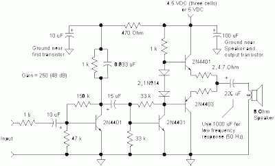
The amplifier may be modified to work with a 9 volt battery if desired by moving the output transistors' bias point. Lowering the 33k resistor connected from the second transistor's base to ground to about 10k will move the voltage on the output electrolytic capacitor to about 1/2 the supply voltage.
This bias change gives more signal swing before clipping occurs and this change is not necessary if the volume is adequate. As before, the two 4.7 ohm resistors may be replaced with a single 10 ohm resistor in series with either emitter.
This bias change gives more signal swing before clipping occurs and this change is not necessary if the volume is adequate. As before, the two 4.7 ohm resistors may be replaced with a single 10 ohm resistor in series with either emitter.
Saturday, 24 December 2016
Battery Charger Small LED Lamp based Solar Cell Photovoltaic

This is the circuit diagram of rechargable battery charger which use solar cell / photovoltaic as the DC source. This circuit works to charge 3 types of rechargable batteries that are lead acid, Ni-Cd and Li-ion. The lead-acid batteries are generally utilized in emergency lamps and UPS. The photovoltaic module or solar cell explained in this post is capable of producing a power of 5 watts. At full sunlight, the solar cell outputs 16.5V. It can deliver a current of 300-350 mA.
How the circuit works?
The working of the circuit is quite simple. The output of the solar panel is fed via diode 1N5402 (D1), which acts as a polarity guard and protects the solar panel. An ammeter is connected in series between diode D1 and fuse to measure the current flowing during charging of the batteries. As shown in Image #1, we have used an analogue multimeter in 500mA range. Diode D2 is used for protection against reverse polarity in case of wrong connection of the lead-acid battery. When you connect wrong polarity, the fuse will blow up.
For charging a lead-acid battery, shift switch S1 to ‘on’ position and use connector ‘A.’ After you connect the battery, charging starts from the solar panel via diode D1, multimeter and fuse. Note that pulsating DC is the best for charging lead-acid batteries. If you use this circuit for charging a lead-acid battery, replace it with a normal pulsating DC charger once a week. Keep checking the water level of the leadacid battery. Pure DC voltage normally leads to deposition of sulphur on the plates of lead-acid batteries.
For charging Li-ion battery (used in mobile phones), shift switches S1 and S2 to ‘on’ position and use connector ‘C.’ Regulator IC 7805 (IC2) provides 5V for charging the Li-ion battery. Using this circuit, you can charge a 3.6V Li-ion cell very easily. Resistor R3 limits the charging current. Image #2 shows the circuit for a small LED-based lamp. It is simple and lowcost. Six 10mm white LEDs (LED2 through LED7) are used here. Just connect them in parallel and drive directly by a 3.6V DC source. You can use either pencil-type Ni-Cd batteries or rechargeable batteries as the power source.
Assemble the circuit on a general purpose PCB and enclose in a small box. Mount RCA socket on the front panel of the box and wire RCA plug with cable for connecting the battery and LED based lamp to the charger.
With this circuit, you can save on your electricity bills by switching to alternative sources of power.
Friday, 16 December 2016
Simple 2 Watt Small Switching Power Supply Circuit Diagram
In this small switching power supply, a Schmitt trigger oscillator is used to drive a switching transistor that supplies current to a small inductor. Energy is stored in the inductor while the transistor is on, and released into the load circuit when the transistor switches off.
2 Watt Small Switching Power Supply Circuit Diagram
2 Watt Small Switching Power Supply Circuit Diagram

The output voltage is dependent on the load resistance and is limited by a zener diode that stops the oscillator when the voltage reaches about 14 volts. Higher or lower voltages can be obtained by adjusting the voltage divider that feeds the zener diode. The efficiency is about 80% using a high Q inductor.
Subscribe to:
Posts (Atom)