Showing posts with label Transistor. Show all posts
Showing posts with label Transistor. Show all posts
Tuesday, 7 March 2017
In Circuit Transistor Checker
This simple circuit has helped me out on many occasions. It is able to check transistors, in the circuit, down to 40 ohms across the collector-base or base-emitter junctions. It can also check the output power transistors on amplifier circuits. Circuit operation is as follows. The 555 timer ( IC1 ) is set up as a 12hz multi vibrator. The output on pin 3 drives the 4027 flip-flop ( IC2). This flip-flop divides the input frequency by two and delivers complementary voltage outputs to pin 15 and 14. The outputs are connected to LED1 and LED2 through the current limiting resistor R3.
Circuit Diagram
 The LED's are arranged so that when the polarity across the circuit is one way only one LED will light and when the polarity reverses the other LED will light, therefore when no transistor is connected to the tester the LED's will alternately flash. The IC2 outputs are also connected to resistors R4 and R5 with the junction of these two resistors connected to the base of the transistor being tested. With a good transistor connected to the tester, the transistor will turn on and produce a short across the LED pair. If a good NPN transistor is connected then LED1 will flash by itself and if a good PNP transistor is connected then LED2 will flash by itself. If the transistor is open both LED's will flash and if the transistor is shorted then neither LED will flash.
Saturday, 28 January 2017
Simple Timer with Transistor Circuit Diagram
The below Simple Timer with Transistor Circuit Diagram is a simple timer that uses only two Darlington transistors and a capacitor base to generate a delay. When SW1 is pressed, the timer starts, the time setting is set by VR1. The duration of the timer is given by the values of the potentiometer VR1 and the capacitor C1 that this circuit is 220 pF. To reach other durations of time must change the values of these two components.
Timer with Transistor Circuit Diagram

Sunday, 8 January 2017
Transistor As a timer circuit
Basically on all timer or timer circuit utilizing most of the basic characteristics of the capacitor.

The basic characteristic is the process of filling and discharge that occurs in the capacitor. The length of time charging and release depends on the value of the capacitor.
If we observe the above circuit, the light will immediately switch SW1 turns on when we plug it into potensio VR1, this is because the current flowing from VR1 to trigger the transistor base should fill the first capacitor C1. Semakian large capacitance value of C1 then the longer the time required by the transistor to turn on the lights. Then if we connect it to the Ground SW1 then light would soon die and the capacitor will immediately clear the cargo. So can we draw the conclusion that the transistor can be used as a timer circuit using capacitor charging and discharging properties.
Monday, 2 January 2017
AB Transistor Audio Power Amplifier Circuit Diagram
This is a class AB transistor power amplifier. It is a simple amplifier to build, uses standard parts and is stable and reliable. The entire circuit utilizes commonly available components and may be simply built over a general-purpose board. But this amplifier has very good sound quality.
AB Transistor Audio Power Amplifier Circuit Diagram
AB Transistor Audio Power Amplifier Circuit Diagram

There are eleven transistors, including four in the output stage. Q1 and Q2 transistor must be between 3 and 5 amperes power transistors. Q4 and Q5 must be between 100mA and 500mA driver transistors. Other transistors are 10mA small driver transistors. Q1, Q4 and Q2, Q5 are complementary pairs, they make complementary darlington pairs.
| PART LIST | |
| R1 | 1.5KΩ ¼W |
| R2 | 150Ω ¼W |
| R3 | 1KΩ ¼W |
| R4 | 0.22Ω 2W |
| R5 | 0.22Ω 2W |
| R6 | 39KΩ ¼W |
| R7 | 1KΩ ¼W |
| R8 | 120Ω ¼W |
| R9 | 6.8KΩ ¼W |
| R10 | 6.8KΩ ¼W |
| R11 | 47KΩ ¼W |
| R12 | 47KΩ ¼W |
| R13 | 2.2KΩ ¼W |
| R14 | 180KΩ ¼W |
| R15 | 18KΩ ¼W |
| C1 | 22pF Ceramic |
| C2 | 4.7µF 16V |
| C3 | 1000µF 25V |
| C4 | 100µF 25V |
| D1 | 1N4148 |
| D2 | 1N4148 |
| Q1 | 2SD313 |
| Q2 | 2SB507 |
| Q3 | 2SA733 |
| Q4 | 2SB560 |
| Q5 | 2SD400 |
| Q6, Q7, Q8, Q9, Q10 | 2SA733 |
| Q11 | 2SD400 |
| LS1 | 4Ω 20W SPEAKER |
| Supply voltage (Vs) | = 20V |
| Speaker impedance (R) | = 4Ω |
| Peak to peak voltage (Vpp) | = 20-2 =18V |
| Peak voltage | = 9V |
| Maximum output (Pmax) | = 9V2/2R |
| = 81/8 | |
| = 10W |
Amplification of this amplifier (A)
| A | = R6/R13+1 |
| = 39KΩ/2.2KΩ+1 | |
| = 18 |
Q1 and Q2 must be kept sufficiently cool, so it is mounted on a suitable heat sink. If you used single heat sink please use insulation between transistors and heat sink.
Thursday, 29 December 2016
4 Transistor Amplifier for Small Speakers Circuit Project
The circuit above shows a 4-transistor utility amplifier suitable for a variety of projects including receivers, intercoms, microphones, telephone pick-up coils, and general audio monitoring. The amplifier has a power isolation circuit and bandwidth limiting to reduce oscillations and "motorboating". The values are not particularly critical and modest deviations from the indicated values will not significantly degrade the performance.
Three cell battery packs giving about 4.5 volts are recommended for most transformerless audio amplifiers driving small 8 ohm speakers. The battery life will be considerably longer than a 9 volt rectangular battery and the cell resistance will remain lower over the life of the battery resulting in less distortion and stability problems.
4 Transistor Amplifier for Small Speakers Circuit
Three cell battery packs giving about 4.5 volts are recommended for most transformerless audio amplifiers driving small 8 ohm speakers. The battery life will be considerably longer than a 9 volt rectangular battery and the cell resistance will remain lower over the life of the battery resulting in less distortion and stability problems.
4 Transistor Amplifier for Small Speakers Circuit
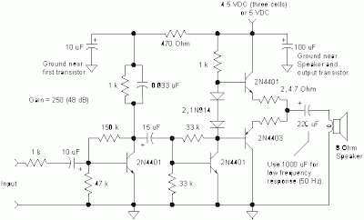
The amplifier may be modified to work with a 9 volt battery if desired by moving the output transistors' bias point. Lowering the 33k resistor connected from the second transistor's base to ground to about 10k will move the voltage on the output electrolytic capacitor to about 1/2 the supply voltage.
This bias change gives more signal swing before clipping occurs and this change is not necessary if the volume is adequate. As before, the two 4.7 ohm resistors may be replaced with a single 10 ohm resistor in series with either emitter.
This bias change gives more signal swing before clipping occurs and this change is not necessary if the volume is adequate. As before, the two 4.7 ohm resistors may be replaced with a single 10 ohm resistor in series with either emitter.
Sunday, 20 November 2016

Subscribe to:
Posts (Atom)