Showing posts with label Amplifier. Show all posts

Friday, 24 March 2017

17 Watt dual BTL Audio Power Amplifier HA13127


17 Watt dual BTL Audio Power Amplifier HA13127
Datasheet for HA13127: Download
Readmore → 17 Watt dual BTL Audio Power Amplifier HA13127

Thursday, 23 March 2017

TDA7490 Audio Amplifier 2 x 25W 1 x 50W


TDA7490 general description:


The TDA7490 is a dual audio class D amplifier assembled in Flexiwatt 25 package; it is specially designed for high efficiency application mainly for TV and Home Stereo sets.  TDA7490 Audio Amplifier 2 x 25W / 1 x 50W


TDA7490 features:

  • 25W + 25W OUTPUT POWER:
  • RL = 8Ω/4Ω; THD = 10%
  • HIGH EFFICIENCY
  • WIDE SUPPLY VOLTAGE RANGE (FROM
  • ±10 TO ±25V)
  • SPLIT SUPPLY
  • TURN OFF/ON POP FREE
  • ST-BY AND MUTE FEATURES
  • SHORT CIRCUIT PROTECTION ACROSS
  • THE LOAD
  • THERMAL OVERLOAD PROTECTION
  • EXTERNALLY SINCHRONIZABLE
  • BRIDGE CONFIGURATION


TDA7490 sterio circuit diagram:

TDA7490 Audio Amplifier 2 x 25W / 1 x 50W circuit diagram

TDA7490 mono circuit diagram:

TDA7490 Audio Amplifier 2 x 25W / 1 x 50W circuit diagram
TDA7490 Audio Amplifier 2 x 25W / 1 x 50W mono circuit diagram


TDA7490 sterio circuit pcb:

PCB layout TDA7490 Audio Amplifier 2 x 25W / 1 x 50W circuit diagram
TDA 7490 pcb layout 


Readmore → TDA7490 Audio Amplifier 2 x 25W 1 x 50W

Saturday, 18 March 2017

2 X 0 32W BA5386 amplifier schematic


Amplifier circuit above scheme is a combination of the two IC was then made into one of its supply voltage so it does not require a lot of supply voltage and output a stereo input. Output issued also very low at 2 X 0.32 W and has 8 ohm impedance. Indeed, this amplifier has a very low output, but the amplifier is quite easy to make and does not require much cost. The voltage required at least 4 volts while the maximum supply voltage of 12 volts.
BA5386 amplifier
Part List :
R1,R2______50K trim
C1,C2______3u3F
C3,C4______100uF
C5,C6______470uF
U1,U2______BA5386
Readmore → 2 X 0 32W BA5386 amplifier schematic

Friday, 17 March 2017

30W Power Audio Amplifier Circuit Diagram


TIP141 si a npn silicon power darling tons designed for complementary use with TIP145, TIP146 and TP147. Can stand up to 125 W at 25°C Case Temperature, 10 A Continuous Collector Current and has a minimum hFE of 1000 at 4 V, 5 A. This home audio amplifier can output 30W with a +- 32V symmetric power supply. If you want a stereo power amplifier please check out the other schematics.


R1=1Kohm R16-17=270ohm D1=9.1V 0.4W zener
R2=47Kohm R18=22ohm 1W D2-3=1N4148
R3=1.5Kohm R19=NC Q1-2=BC550C
R4-5=10Kohm R20-21=0.39ohm 4W Q3=MPSA56
R6=5.6Kohm TR1=250ohm trimmer Q4=BC547B
R7=10ohm C1=470nF 100V MKT Q5=BC212
R8=47Kohm C2=1nF 100V MKT Q6=BC183
R9=560ohm C3=68pF ceramic Q7-8=MPSAO6
R10-11=8.2Kohm C4-8=22nF 100V MKT Q9=TIP141
R12-15=120ohm C5-6-7=100nF 100V MKT Q10=TIP146
R13=680ohm C9=47uF 25V F1-2=1.6AT FUSE
R14=330ohm C10-11=220uF 63V All the resistors is 1/4W 1% except quote differently

30W power amplifier circuit diagram

30W power amplifier circuit diagram

30 Watt audio amplifier PCB

30 Watt audio amplifier PCB


Readmore → 30W Power Audio Amplifier Circuit Diagram

TA8210AH Stereo Car Power Amplifier


IC TA8210AH By using this you can apply a series of audio power amplifier is the car audio system. In general, all the speakers in the car using a subwoofer speaker, and woofer. Because the car is not big room so the sound is being required is not too high.

Audio amplifier circuit can work at a minimum voltage 12-volt DC, if supplied under voltage 12-volt amplifier work will be less than the maximum. This amplifier output power up to 200W or 2 x 100W stereo with 8 ohm impedance.


200W car amplifier schematic

Part List :

Resistor

R1 =1K

R2 =50K trim

R3 =1K

R4 =50K trim

R5 =680R

R6 =680R

R7 =150K

R8 =2R2

R9 =2R2

R10=2R2

R11=2R2


Capacitor

C1 =1uF

C2 =1uF

C3 =47uF

C4 =47uF

C5 =100n/400V

C6 =220uF

C7 =220uF

C8 =100n/400V

C9 =100n/400V

C10=100n/400V


Intregated Circuit

IC1=TA8210AH


Connector

X2-3=in R

X2-2=gnd

X2-1=in L

X1-1,X1-2=Out R

X1-3,X1-4=Out L
Readmore → TA8210AH Stereo Car Power Amplifier

Wednesday, 15 March 2017

22 Watt Car Subwoofer Amplifier


22W into 4 Ohm power amplifier, Variable Low Pass Frequency: 70 – 150Hz
This unit is intended to be connected to an existing car stereo amplifier, adding the often required extra "punch" to the music by driving a subwoofer. As very low frequencies are omnidirectional, a single amplifier is necessary to drive this dedicated loudspeaker. The power amplifier used is a good and cheap BTL (Bridge Tied Load) 13 pin IC made by Philips (now NXP Semiconductors) requiring a very low parts count and capable of delivering about 22W into a 4 Ohm load at the standard car battery voltage of 14.4V.
.
Circuit diagram:
22 Watt Car Subwoofer Amplifier Circuit Diagram22 Watt Car Subwoofer Amplifier Circuit Diagram

Parts:
P1_____________10K Log Potentiometer
P2_____________22K Dual gang Linear Potentiometer
R1,R4___________1K 1/4W Resistors
R2,R3,R5,R6____10K 1/4W Resistors
R7,R8_________100K 1/4W Resistors
R9,R10,R13_____47K 1/4W Resistors
R11,R12________15K 1/4W Resistors
R14,R15,R17____47K 1/4W Resistors
R16_____________6K8 1/4W Resistor
R18_____________1K5 1/4W Resistor
C1,C2,C3,C6_____4µ7 25V Electrolytic Capacitors
C4,C5__________68nF 63V Polyester Capacitors
C7_____________33nF 63V Polyester Capacitor
C8,C9_________220µF 25V Electrolytic Capacitors
C10___________470nF 63V Polyester Capacitor
C11___________100nF 63V Polyester Capacitor
C12__________2200µF 25V Electrolytic Capacitor
D1______________LED any color and type
Q1,Q2_________BC547 45V 100mA NPN Transistors
IC1___________TL072 Dual BIFET Op-Amp
IC2_________TDA1516BQ 24W BTL Car Radio Power Amplifier IC
SW1____________DPDT toggle or slide Switch
SW2____________SPST toggle or slide Switch capable of withstanding a current of at least 3A
J1,J2__________RCA audio input sockets
SPKR___________4 Ohm Woofer or two 8 Ohm Woofers wired in parallel

The stereo signals coming from the line outputs of the car radio amplifier are mixed at the input and, after the Level Control, the signal enters the buffer IC1A and can be phase reversed by means of SW1. This control can be useful to allow the subwoofer to be in phase with the loudspeakers of the existing car radio. Then, a 12dB/octave variable frequency Low Pass filter built around IC1B, Q1 and related components follows, allowing to adjust precisely the low pass frequency from 70 to 150Hz. Q2, R17 and C9 form a simple dc voltage stabilizer for the input and filter circuitry, useful to avoid positive rail interaction from the power amplifier to low level sections.
Notes:
  • IC2 must be mounted on a suitable finned heatsink
  • Due to the long time constant set by R17 and C9 in the dc voltage stabilizer, the whole amplifier will become fully operative about 15 - 30 sec. after switch-on.
Technical data:
Output power (1KHz sinewave):
22W RMS into 4 Ohms at 14.4V supply
Sensitivity:
250mV input for full output
Frequency response:
20Hz to 70Hz -3dB with the cursor of P2 fully rotated towards R12
20Hz to 150Hz -3dB with the cursor of P2 fully rotated towards R11
Total harmonic distortion:
17W RMS: 0.5% 22W RMS: 10%


Readmore → 22 Watt Car Subwoofer Amplifier

Monday, 13 March 2017

50W audio amplifier LM3876 Circuit Diagram


LM3876 is a high performance audio power amplifier IC from National Semiconductors. The LM3876 can deliver 50watts of output power into an 8 ohm loudspeaker. LM3876 has excellent signal to noise ratio and has wide supply voltage range. Other features of LM3876 are output to ground short circuit protection, input mute function, and output over voltage protection, etc. Applications of LM3876 are component stereo, compact stereo, surround systems, self powered speakers, etc.
Circuit diagram :
50-w-audio-amplifer-circuit diagram
50W audio amplifier Circuit Diagram
The 50 watt audio amplifier  circuit shown below is designed based on the application diagram from the data sheet of LM3876. Some modifications are made on the original circuit for improving the performance. The bipolar electrolytic capacitor C7 is the input DC decoupling capacitor. R4 is the input resistance. R2 & R1 and bipolar electrolytic capacitor C5 forms a feedback circuit. C2, C1 are filter/by-pass capacitors for the positive supply rail. C4 & C3 are the filters/by-pass capacitors for the negative supply rail. The feedback resistor R2 sets the gain of the amplifier. L1 provides high impedance at high frequencies so that R7 may decouple capacitive loads. R3 is the mute resistance which allows 0.5mA to be drawn from pin8 to turn the mute function OFF. S1 is the mute switch. Resistor R6 and capacitor C8 forms a Zobel network which improves the high frequency stability of the amplifier and prevents oscillations.
Notes :
  • The LM3876 can be operated from a supply voltage range of +/-12V to +/-49V DC.
  • I recommend +/-35V DC for powering the IC.
  • LM3876 requires a proper heat sink.
  • Quiescent current of LM3876 is around 70mA


Readmore → 50W audio amplifier LM3876 Circuit Diagram

Simple Amplifier Schematic


This Circuit Use a IC BA515 for operation it. This is very simple Amplifier schematic , with only add 8 component , such as resistor and capacitor. Minimum voltage require 3 Volt , this also low voltage amplifier . And maximum voltage require 9 volt. Power output under 10 Watt with impedance 4 Ohm. This circuit is very suitable for small speakers.
See schematic below :


If the circuit above not working may cause as follows :
- Check voltage on the circuit , wether or not the voltage.
- Check wether the components are soldered onto PCB properly.
- Check input and output  wether working or not.
- Check input output cable , if there are disconnected , or a short circuit. Or input connected with ground.
Readmore → Simple Amplifier Schematic

Sunday, 12 March 2017

Simple Surround audio amplifier circuit based on the IC TDA7053


Perhaps the surround amplifier circuit below is an interesting circuit is made. For, making easy just by using the IC and electrolytic capacitor added 1 , we already can hear the strains of music with sound ( Front Left ,Right and surround Right , Left. In addition to listening to music , this amplifier is also very suitable for gamers who want good sound quality.
Minimum voltage requred 9 volts and maximum of 15 volts. Power Output of each speaker 10 Watt with 4 ohm impedance.

Readmore → Simple Surround audio amplifier circuit based on the IC TDA7053

Tuesday, 7 March 2017

TDA8569Q Audio Amplifier 4 x 40W


TDA8569Q general description:


The TDA8569Q is an integrated class-B output amplifier in a 23-lead Single-In-Line (SIL) plastic power package. It contains four amplifiers in Bridge-Tied Load (BTL) configuration, each with a gain of 26 dB. The output power is 4 × 40 W in a 2 Ω load.  TDA8569Q Audio Amplifier 4 x 40W

TDA8569Q features:

Capable of driving 2 Ω loads
Requires very few external components
High output power
Low output offset voltage
Fixed gain
Diagnostic facility (distortion, short-circuit and temperature pre-warning)
Good ripple rejection
Mode select switch (operating, mute and standby)
Load dump protection
Short-circuit safe to ground, to VP and across the load
Low power dissipation in any short-circuit condition
Thermally protected
Reverse polarity safe
Electrostatic discharge protection
No switch-on/switch-off plop
Flexible leads
Low thermal resistance
Pin compatible with the TDA8567Q.

TDA8569Q circuit diagram:

4 x 40W TDA8569Q Audio Amplifier
4 x 40W TDA8569Q Audio Amplifier 


TDA8569Q layout:

layout for 4 x 40W TDA8569Q Audio Amplifier
layout for 4 x 40W TDA8569Q Audio Amplifier 


pcb for layout for 4 x 40W TDA8569Q Audio Amplifier
pcb for layout for 4 x 40W TDA8569Q Audio Amplifier


Readmore → TDA8569Q Audio Amplifier 4 x 40W

Monday, 6 March 2017

Circuit Guards Amplifier Outputs Against Overvoltage


A universal requirement for automotive electronics is that any device with direct connections to the wiring harness must be able to withstand shorts to the battery voltage. Though brutal, this requirement is necessary for reliability and for safety. One example of the need for this protection is an audio amplifier that produces indicator noises in the automotive interior. Though operating from a voltage of 3.3 or 5V, which is lower than the battery voltage, the amplifier must be able to stand off the full battery voltage.

Circuit diagram :

amplifier outputs against overvoltage

Figure 1 : This output circuit provides continuose protection against overvoltge faults

You can also use a protection network appropriate for these amplifiers for other automotive circuits (Figure 1). A dual N-channel MOSFET disconnects the amplifier’s outputs from the wiring harness in response to a high-voltage condition on either output. The MOSFETs, Q1A and Q1B, are normally on; zener diode D4 and its bias components drive the MOSFETs’ gates to approximately 11V. Dual diode D3 provides a diode-OR connection to the dc voltage on each output, thereby producing a voltage that controls the output of shunt regulator IC2. The circuitry protects IC1, a 1.4W Class AB amplifier suitable for audible warnings and indications for the automotive electronics.

During normal operation, the amplifier outputs’ dc components are at one-half of the VCC supply—2.5V in this case, for which VCC is 5V. The 11V gate drive fully enhances the MOSFETs, and the shunt-regulator output is off because its feedback input, Pin 5, is below its internal 0.6V threshold. If either output exceeds 5V, current flows through D3 into the R5/R6 divider, pulling the feedback terminal above its threshold. The shunt-regulator output then pulls the MOSFET-gate voltage from 11V almost to ground, which blocks high voltage from the amplifier by turning off the MOSFETs. The MOSFETs easily withstand the continuous output voltage, and the circuit returns to normal operation when you remove the short. Because the circuit does not respond instantaneously, zener diodes D1 and D2 provide protection at the beginning of a fault condition.

Figure 2. Figure 2. In Figure 1, one of U1's two audio outputs (top trace) is protected when its external terminal accidentally contacts an 18V supply voltage (2nd trace).


The waveforms of Figure 2 represent an operating circuit. One of the amplifier’s outputs (Trace 1) is a 1-kHz sine wave biased at a dc voltage of 2.5V. Trace 2 is the signal on the wire harness. It also starts as a 1-kHz sine wave biased at a 2.5V-dc voltage, but, at 200 µsec, it shorts to an 18V supply. Trace 3 is the shunt regulator’s output, initially biased at 11V but pulled to ground in response to the overvoltage condition. Trace 4 is current in the wire harness. Initially a sine wave, this current drops to zero in response to the overvoltage condition.

The components in Figure 1 optimize this circuit for 5V operation. For other voltages, you can adjust the R5/R6 resistor values. The shunt regulator must be able to function in saturation and, therefore, requires a separate supply pin in addition to the shunt output pin. The circuit repeatedly withstands 28V shorts without damage.


Source : www.maxim-ic.com


Readmore → Circuit Guards Amplifier Outputs Against Overvoltage

Wednesday, 1 March 2017

TDA1599 IF amplifier demodulator for FM radio receivers


Circuit Diagram:
TDA1599 IF amplifier/demodulator for FM radio receivers
Datasheet for TDA1599: Download
Readmore → TDA1599 IF amplifier demodulator for FM radio receivers

Wednesday, 22 February 2017

Battery powered Headphone Amplifier


Low distortion Class-B circuitry 6V Battery Supply. Some lovers of High Fidelity headphone listening prefer the use of battery powered headphone amplifiers, not only for portable units but also for home "table" applications. This design is intended to fulfil their needs and its topology is derived from the Portable Headphone Amplifier featuring an NPN/PNP compound pair emitter follower output stage. 

An improved output driving capability is gained by making this a push-pull Class-B arrangement. Output power can reach 100mW RMS into a 16 Ohm load at 6V supply with low standing and mean current consumption, allowing long battery duration. The single voltage gain stage allows the easy implementation of a shunt-feedback circuitry giving excellent frequency stability.
.
Battery-powered Headphone Amplifier Circuit Diagram :
Battery-powered Headphone Amplifier Circuit diagram


Notes:
  • For a Stereo version of this circuit, all parts must be doubled except P1, SW1, J2 and B1.
  • Before setting quiescent current rotate the volume control P1 to the minimum, Trimmer R6 to maximum resistance and Trimmer R3 to about the middle of its travel.
  • Connect a suitable headphone set or, better, a 33 Ohm 1/2W resistor to the amplifier output.
  • Switch on the supply and measure the battery voltage with a Multimeter set to about 10Vdc fsd.
  • Connect the Multimeter across the positive end of C4 and the negative ground.
  • Rotate R3 in order to read on the Multimeter display exactly half of the battery voltage previously measured.
  • Switch off the supply, disconnect the Multimeter and reconnect it, set to measure about 10mA fsd, in series to the positive supply of the amplifier.
  • Switch on the supply and rotate R6 slowly until a reading of about 3mA is displayed.
  • Check again the voltage at the positive end of C4 and readjust R3 if necessary.
  • Wait about 15 minutes, watch if the current is varying and readjust if necessary.
  • Those lucky enough to reach an oscilloscope and a 1KHz sine wave generator, can drive the amplifier to the maximum output power and adjust R3 in order to obtain a symmetrical clipping of the sine wave displayed.
Technical data:
Output power (1KHz sinewave):
    16 Ohm: 100mW RMS
    32 Ohm: 60mW RMS
    64 Ohm: 35mW RMS
    100 Ohm: 22.5mW RMS
    300 Ohm: 8.5mW RMS
Sensitivity:
    160mV input for 1V RMS output into 32 Ohm load (31mW)
    200mV input for 1.27V RMS output into 32 Ohm load (50mW)
Frequency response @ 1V RMS:
    flat from 45Hz to 20KHz, -1dB @ 35Hz, -2dB @ 24Hz
Total harmonic distortion into 16 Ohm load @ 1KHz:
    1V RMS (62mW) 0.015% 1.27V RMS (onset of clipping, 100mW) 0.04%
Total harmonic distortion into 16 Ohm load @ 10KHz:
    1V RMS (62mW) 0.05% 1.27V RMS (onset of clipping, 100mW) 0.1%
Unconditionally stable on capacitive loads


Source : red circuits


Readmore → Battery powered Headphone Amplifier

Tuesday, 21 February 2017

STK013 Amplifier Circuit


On the amplifier circuit using ic STK, the same as my previous posting. However, in the above circuit has 2 inputs and 2 outputs, or commonly called a stereo amplifier. This issue of power amplifier 2 x 18Watt and has impedance 8. To stress that it takes about 35-38Volt.
stk 013 amplifier
Component list :
Resistor
R1 =  390K
R2 = 390K
R3 = 220K
R4 = 220K
R5 = 220K
R6 = 220K
R7 = 100R
R8 = 1R
R9 = 9.1K
R10 = 9.1K
R11 = 1R
Capacitor
C1 = 10uF
C2 = 10uF
C3 = 0.47uF
C4 = 0.47uF
C5 = 220uF
C6 = 0.047uF
C7 = 4700uF
C8 = 100uF
C9 = 1000uF
C10 = 100uF
C11 = 4700uF
C12 = 470uF
C13 = 0.047uF
IC
U1 = STK013
Readmore → STK013 Amplifier Circuit

Monday, 20 February 2017

Class A Headphone Amplifier


This circuit is derived from the Portable Headphone Amplifier featuring an NPN/PNP compound pair emitter follower output stage. An improved output driving capability is gained by making this a push-pull Class-A arrangement. Output power can reach 427mW RMS into a 32 Ohm load at a fixed standing current of 100mA. The single voltage gain stage allows the easy implementation of a shunt-feedback circuitry giving excellent frequency stability.

Class-A Headphone Amplifier-Circuit Diagram
Class-A Headphone Amplifier Circuit diagram

The above mentioned shunt-feedback configuration also allows the easy addition of frequency dependent networks in order to obtain an useful, unobtrusive, switchable Tilt control (optional). When SW1 is set in the first position a gentle, shelving bass lift and treble cut is obtained. The central position of SW1 allows a flat frequency response, whereas the third position of this switch enables a shelving treble lift and bass cut.
Note:
  • Before setting quiescent current rotate the volume control P1 to the minimum, Trimmer R6 to zero resistance and Trimmer R3 to about the middle of its travel.
  • Connect a suitable headphone set or, better, a 33 Ohm 1/2W resistor to the amplifier output.
  • Connect a Multimeter, set to measure about 10Vdc fsd, across the positive end of C5 and the negative ground.
  • Switch on the supply and rotate R3 in order to read about 7.7-7.8V on the Multimeter display.
  • Switch off the supply, disconnect the Multimeter and reconnect it, set to measure at least 200mA fsd, in series to the positive supply of the amplifier.
  • Switch on the supply and rotate R6 slowly until a reading of about 100mA is displayed.
  • Check again the voltage at the positive end of C5 and readjust R3 if necessary.
  • Wait about 15 minutes, watch if the current is varying and readjust if necessary.
Parts List :
P1 : 22K Dual gang Log Potentiometer 
R1 : 15K
R2 : 220K
R3 : 100K
R4 : 33K
R5 : 68K
R6 : 50K
R7 : 10K
R8,R9 : 47K
R10,R11 : 2R2
R12 : 4K7
R13 : 4R7
R14 : 1K2
R15,R18 : 330K
R16 : 680K
R17,R19 : 220K
R20,R21 : 22K
C1,C2,C3,C4 : 10µF/25V
C5,C7 : 220µF/25V
C6,C11 : 100nF
C8 : 2200µF/25V
C9,C12 : 1nF
C10 : 470pF
C13 : 15nF
D1 : LED
D2,D3 : 1N4002
Q1,Q2 : BC550C
Q3 : BC560C
Q4 : BD136
Q5 : BD135
IC1 : 7815
T1 : 15CT/5VA Mains transformer
SW1 : 4 poles 3 ways rotary Switch
SW2 : SPST slide or toggle Switch


Readmore → Class A Headphone Amplifier

Friday, 3 February 2017

TDA7294 Amplifier Circuits


TDA7294 Audio Amplifier Circuits

TDA7294 is a monolithic integrated circuit in Multiwatt15 package, with high output power (up to 100W) intended for use as audio class AB amplifier in Hi-Fi field applications (Home Stereo, self powered loudspeakers, Topclass TV). Thanks to the wide voltage range and to the high out current capability it is able to supply the highest power into both 4W and 8W loads even in presence of poor supply regulation, with high Supply Voltage Rejection.

TDA7294 Amplifier Circuits

TDA7294 Amplifier Circuits
TDA7294 Amplifier Circuits pcb

TDA7294 Amplifier Circuits layoput
TDA7294 Amplifier Circuits layout


Readmore → TDA7294 Amplifier Circuits

Wednesday, 1 February 2017

200W K1058 J162 MOSFET Class A Audio Amplifier Circuit


J162 K1058 MOSFET amplifier circuit. Welcome to Free dot com circuit we want audio amplifier circuit, as amp is currently composed of two completely separate mono amplifiers for each channel has its own power supply, inter-channel crosstalk zero, a common phenomenon in amplifiers, the same the diet. 40VAC at 640VA to evaluate the performance of a transformer in order to obtain full 40VAC – 0 -.

Unlike many designs that deliver on the capacitors, the current peaks, I prefer the raw power available from the transformer are in rapid transients.

K1058 J162 200 Watts MOSFET amplifier circuit class-A. Although RAS-300 specifications moderate when they hear, immediately causing the huge reserves of power available and not out of fear that something would result in a very strong during the conduct of the amplifier.

Readmore → 200W K1058 J162 MOSFET Class A Audio Amplifier Circuit

Friday, 27 January 2017

TDA7384 4 x 22W car power amplifier


TDA7384 - 4 x 22W car power amplifier

TDA7384 - 4 x 22W car power amplifierIf connect to car battery where operating voltage is about 13.2V, then each channel can give 22W(4Ω) – what is more than enough for me. This amplifier I probably will use to test audio processor TDA7313 which is stil in development phase.
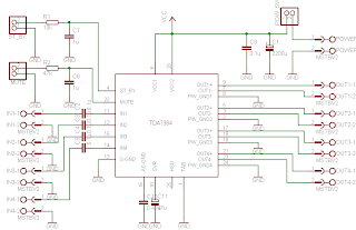

I didn’t find much information about this chip on the internet so I decided to built it and try on my own. As datasheets of TDA7384 says it is low distortion, low output noise, low external component count. Also has Stand-By function and Mute function. It has several protections like from output short circuit to GND or to Vs, capable to handle very inductive loads, thermal limiter, load dump voltage. TDA7384 is an AB power amplifier cased in flexiwatt25 (eagle library is included in project archive) package wich is designed for high end car radio applications. It allows rail to rail output voltage swing with no need of boot-strap capacitors.

Schematics TDA7384
Schematics TDA7384


I have followed the schematic in datasheed when building circuit. In datasheet you may also find PCB layout but it is two layered and didn’t fit to may box I’ve chosen. So I have made single sided PCB 50X100mm.


PCB TDA7384 amplifier

As I put pins on PCB for ST-BY and Mute but I not using them, I connected these pins to VCC like it is shown in PCB view. According to datasheet St-By and Mute turns off amplifier if signal in input is lower than 3.5V. So it is recommended to connect these pins to Vcc if not used.
Maximum power dissipation of chip is 80W(Tcase=70ºC), so it can handle 4 channels working at power of 20W each. But of course chip in a box doesn’t have good ventilation so I’ve put a radiator to ensure that amplifier effectively dissipates heats. I didn’t try to load amplifier to maximum to se if it doesn’t heat up to much. But at normal sound level it stays warm what is normal.


On box amplifier
On box amplifier


Dont forget to put thermal paste between chip and radiator to ensure lower thermal resistance. And here we go – brand new power amplifier ready to go:


TDA7384 Already to use
Already to use


source: [link]

Readmore → TDA7384 4 x 22W car power amplifier

Wednesday, 25 January 2017

Power amplifier circuit 60 W mono


Wow this is nice intregated amplifier circuit , because this IC can be power output up to 60 Watt . With minimum require voltage 8 V , and maximum voltage 35 V . But this circuit is'nt so good to working on car , because output sound is very loud but not smooth. Amplifier so good working on full range , with speaker full range 100W and impedance 8 Ohm.
Below it is schematic :


Click to view large

The circuit above use IC AN7170 , the original output power IC is 20 W with impedance. But with use the circuit output elevated up to 60W.

Readmore → Power amplifier circuit 60 W mono

35W 4 Channel Amplifier for car audio AN7555NZ


35W 4-Channel Amplifier for car audio
Datasheet for AN7555NZ: Download
Readmore → 35W 4 Channel Amplifier for car audio AN7555NZ