Showing posts with label Audio. Show all posts

Wednesday, 29 March 2017

Telephone line Based Audio Muting and Light On Circuit


Telephone line Based Audio Muting and Light-On Circuit. Very often when enjoying music or watching TV at high audio level, we may not be able to hear a telephone ring and thus miss an important incoming phone call. To overcome this situation, the circuit presented here can be used. The circuit would automatically light a bulb on arrival of a telephone ring and simultaneously mute the music system/TV audio for the duration the telephone handset is off-hook. Lighting of the bulb would not only indicate an incoming call but also help in locating the telephone during darkness.
.
Circuit diagram :
Telephone line Based Audio Muting and Light-On Circuit Diagram Telephone line Based Audio Muting and Light-On Circuit Diagram 
.
On arrival of a ring, or when the handset is off-hook, the inbuilt transistor of IC1 (opto-coupler) conducts and capacitor C1 gets charged and, in turn, transistor T1 gets forward biased. As a result, transistor T1 conducts, causing energisation of relays RL1, RL2, and RL3. Diode D1 connected in antiparallel to inbuilt diode of IC1, in shunt with resistor R1, provides an easy path for AC current and helps in limiting the voltage across inbuilt diode to a safe value during the ringing. (The RMS value of ring voltage lies between 70 and 90 volts RMS.) Capacitor C1 maintains necessary voltage for continuously forward biasing  transistor T1 so that the relays are not energised during the negative half cycles and off-period of ring signal. Once the handset is picked up, the relays will still remain energised because of low impedance DC path available (via cradle switch and handset) for the in-built diode of IC1. 

After completion of call when handset is placed back on its cradle, the low-impedance path through handset is no more available and thus relays RL1 through RL3 are deactivated. As shown in the figure, the energised relay RL1 switches on the light, while energisation of relay RL2 causes the path of TV speaker lead to be opened. (For dual-speaker TV, replace relay RL2 with a DPDT relay of 6V, 200 ohm.) Similarly, energisation of DPDT relay RL3 opens the leads going to the speakers and thus mutes both audio speakers. Use ‘NC’ contacts of relay RL3 in series with speakers of music system and ‘NC’ contacts of RL2 in series with TV speaker. Use  ‘NO’ con-tact of relay RL1 in series with a bulb to get the visual indication. 


Author : Dhurjati Sinha - Copyright : EFYmag

Readmore → Telephone line Based Audio Muting and Light On Circuit

Friday, 24 March 2017

17 Watt dual BTL Audio Power Amplifier HA13127


17 Watt dual BTL Audio Power Amplifier HA13127
Datasheet for HA13127: Download
Readmore → 17 Watt dual BTL Audio Power Amplifier HA13127

Thursday, 23 March 2017

TDA7490 Audio Amplifier 2 x 25W 1 x 50W


TDA7490 general description:


The TDA7490 is a dual audio class D amplifier assembled in Flexiwatt 25 package; it is specially designed for high efficiency application mainly for TV and Home Stereo sets.  TDA7490 Audio Amplifier 2 x 25W / 1 x 50W


TDA7490 features:

  • 25W + 25W OUTPUT POWER:
  • RL = 8Ω/4Ω; THD = 10%
  • HIGH EFFICIENCY
  • WIDE SUPPLY VOLTAGE RANGE (FROM
  • ±10 TO ±25V)
  • SPLIT SUPPLY
  • TURN OFF/ON POP FREE
  • ST-BY AND MUTE FEATURES
  • SHORT CIRCUIT PROTECTION ACROSS
  • THE LOAD
  • THERMAL OVERLOAD PROTECTION
  • EXTERNALLY SINCHRONIZABLE
  • BRIDGE CONFIGURATION


TDA7490 sterio circuit diagram:

TDA7490 Audio Amplifier 2 x 25W / 1 x 50W circuit diagram

TDA7490 mono circuit diagram:

TDA7490 Audio Amplifier 2 x 25W / 1 x 50W circuit diagram
TDA7490 Audio Amplifier 2 x 25W / 1 x 50W mono circuit diagram


TDA7490 sterio circuit pcb:

PCB layout TDA7490 Audio Amplifier 2 x 25W / 1 x 50W circuit diagram
TDA 7490 pcb layout 


Readmore → TDA7490 Audio Amplifier 2 x 25W 1 x 50W

Friday, 17 March 2017

30W Power Audio Amplifier Circuit Diagram


TIP141 si a npn silicon power darling tons designed for complementary use with TIP145, TIP146 and TP147. Can stand up to 125 W at 25°C Case Temperature, 10 A Continuous Collector Current and has a minimum hFE of 1000 at 4 V, 5 A. This home audio amplifier can output 30W with a +- 32V symmetric power supply. If you want a stereo power amplifier please check out the other schematics.


R1=1Kohm R16-17=270ohm D1=9.1V 0.4W zener
R2=47Kohm R18=22ohm 1W D2-3=1N4148
R3=1.5Kohm R19=NC Q1-2=BC550C
R4-5=10Kohm R20-21=0.39ohm 4W Q3=MPSA56
R6=5.6Kohm TR1=250ohm trimmer Q4=BC547B
R7=10ohm C1=470nF 100V MKT Q5=BC212
R8=47Kohm C2=1nF 100V MKT Q6=BC183
R9=560ohm C3=68pF ceramic Q7-8=MPSAO6
R10-11=8.2Kohm C4-8=22nF 100V MKT Q9=TIP141
R12-15=120ohm C5-6-7=100nF 100V MKT Q10=TIP146
R13=680ohm C9=47uF 25V F1-2=1.6AT FUSE
R14=330ohm C10-11=220uF 63V All the resistors is 1/4W 1% except quote differently

30W power amplifier circuit diagram

30W power amplifier circuit diagram

30 Watt audio amplifier PCB

30 Watt audio amplifier PCB


Readmore → 30W Power Audio Amplifier Circuit Diagram

Monday, 13 March 2017

50W audio amplifier LM3876 Circuit Diagram


LM3876 is a high performance audio power amplifier IC from National Semiconductors. The LM3876 can deliver 50watts of output power into an 8 ohm loudspeaker. LM3876 has excellent signal to noise ratio and has wide supply voltage range. Other features of LM3876 are output to ground short circuit protection, input mute function, and output over voltage protection, etc. Applications of LM3876 are component stereo, compact stereo, surround systems, self powered speakers, etc.
Circuit diagram :
50-w-audio-amplifer-circuit diagram
50W audio amplifier Circuit Diagram
The 50 watt audio amplifier  circuit shown below is designed based on the application diagram from the data sheet of LM3876. Some modifications are made on the original circuit for improving the performance. The bipolar electrolytic capacitor C7 is the input DC decoupling capacitor. R4 is the input resistance. R2 & R1 and bipolar electrolytic capacitor C5 forms a feedback circuit. C2, C1 are filter/by-pass capacitors for the positive supply rail. C4 & C3 are the filters/by-pass capacitors for the negative supply rail. The feedback resistor R2 sets the gain of the amplifier. L1 provides high impedance at high frequencies so that R7 may decouple capacitive loads. R3 is the mute resistance which allows 0.5mA to be drawn from pin8 to turn the mute function OFF. S1 is the mute switch. Resistor R6 and capacitor C8 forms a Zobel network which improves the high frequency stability of the amplifier and prevents oscillations.
Notes :
  • The LM3876 can be operated from a supply voltage range of +/-12V to +/-49V DC.
  • I recommend +/-35V DC for powering the IC.
  • LM3876 requires a proper heat sink.
  • Quiescent current of LM3876 is around 70mA


Readmore → 50W audio amplifier LM3876 Circuit Diagram

Sunday, 12 March 2017

Simple Surround audio amplifier circuit based on the IC TDA7053


Perhaps the surround amplifier circuit below is an interesting circuit is made. For, making easy just by using the IC and electrolytic capacitor added 1 , we already can hear the strains of music with sound ( Front Left ,Right and surround Right , Left. In addition to listening to music , this amplifier is also very suitable for gamers who want good sound quality.
Minimum voltage requred 9 volts and maximum of 15 volts. Power Output of each speaker 10 Watt with 4 ohm impedance.

Readmore → Simple Surround audio amplifier circuit based on the IC TDA7053

Wednesday, 8 March 2017

Simple Cell Phone Controlled Audio Video Mute Switch


This is a project of simple circuit of the cell phone-controlled audio/video mute switch. This cell-phone-controlled audio/ video mute switch is highly useful in automobiles. The circuit automatically disconnects power supply to the audio/video system whenever the mobile handset is lifted off the holder for making or receiving a call. You can use any readily available cell-phone holder with some mi-nor alterations or fabricate it yourself as shown in Fig. 1.  
Proposed cell-phone holder Fig. 1: Proposed cell-phone holder
 
The circuit is wired around IC LM555 (IC1), the CMOS version of timer NE555, as shown in Fig. 2. IC1 is used as a medium current line driver with either an inverting or non-inverting output. It can sink (or source) current of up to 50 mA only, so take care while handling it. The audio/video system is connected to the circuit via normally opened (N/O) contacts of the relay.
 
circuit of the cell phone-controlled audio video mute switch Fig. 2: The circuit of the cell phone-controlled audio/video mute switch
 
When the cell phone is in its holder, LDR1 does not receive any light from white LED1 and its resistance is high. As a result, the voltage at pin 2 of IC1 re-mains high to provide a low output at pin 3. The low output of IC1 activates relay RL1 and the audio/video system gets power supply via its N/O contacts. LED3 glows to indicate that the audio/video system is ‘on.’  When the handset is taken off the holder, light rays from LED1 fall on LDR1 and its resistance decreases. As a result, the voltage at pin 2 of IC1 de-creases to provide a high output at its pin 3. The high output of IC1 deactivates relay RL1 and the audio/video system does not get power supply. LED2 glows to indicate that the audio/video system is ‘off.’   Preset VR1 is used to control the sensitivity of the circuit. Zener diode ZD1 is used for protecting white LED1 from the higher voltage. The circuit works off a 12V car battery. Switch S1 can be used to manually switch on/off the audio/video system.
 

Author : T.K. Hareendran - Copyright:  Electronics For You

Readmore → Simple Cell Phone Controlled Audio Video Mute Switch

Tuesday, 7 March 2017

TDA8569Q Audio Amplifier 4 x 40W


TDA8569Q general description:


The TDA8569Q is an integrated class-B output amplifier in a 23-lead Single-In-Line (SIL) plastic power package. It contains four amplifiers in Bridge-Tied Load (BTL) configuration, each with a gain of 26 dB. The output power is 4 × 40 W in a 2 Ω load.  TDA8569Q Audio Amplifier 4 x 40W

TDA8569Q features:

Capable of driving 2 Ω loads
Requires very few external components
High output power
Low output offset voltage
Fixed gain
Diagnostic facility (distortion, short-circuit and temperature pre-warning)
Good ripple rejection
Mode select switch (operating, mute and standby)
Load dump protection
Short-circuit safe to ground, to VP and across the load
Low power dissipation in any short-circuit condition
Thermally protected
Reverse polarity safe
Electrostatic discharge protection
No switch-on/switch-off plop
Flexible leads
Low thermal resistance
Pin compatible with the TDA8567Q.

TDA8569Q circuit diagram:

4 x 40W TDA8569Q Audio Amplifier
4 x 40W TDA8569Q Audio Amplifier 


TDA8569Q layout:

layout for 4 x 40W TDA8569Q Audio Amplifier
layout for 4 x 40W TDA8569Q Audio Amplifier 


pcb for layout for 4 x 40W TDA8569Q Audio Amplifier
pcb for layout for 4 x 40W TDA8569Q Audio Amplifier


Readmore → TDA8569Q Audio Amplifier 4 x 40W

Sunday, 26 February 2017

Audio Milli Volt Meter Circuit Diagram


Build a simple audio Milli volt meter circuit diagram. This Audio Milli Volt Meter Circuit has a flat response from 8Hz to 50 kHz at -3 db on tbe 10-mV range. The upper limit remains the same on tbe less sensitive ranges, but the lower frequency limit covers under 1 Hz.

Simple Audio Milli Volt Meter Circuit Diagram

Simple Audio Milli Volt Meter Circuit Diagram


Sourced By : http://circuitsdiagram-lab.blogspot.com/2013/11/simple-audio-milli-volt-meter-circuit.html

Readmore → Audio Milli Volt Meter Circuit Diagram

Friday, 24 February 2017

Simple Audio Power Meter Circuit


This simple circuit indicates the amount of power that goes to a loudspeaker. The dual-color LED shows green at an applied power level of about 1 watt. At 1.5 watts it glows orange and above 3 watts it is bright red. The circuit is connected in parallel with the loudspeaker connections and is powered from the audio signal. The additional load that this represents is 470 Ohm (R1//R3) will not be a problem for any amplifier. During the positive half cycle of the output signal the green LED in the dual-color LED will be turned on, provided the voltage is sufficiently high.

At higher output voltages, T1 (depending on the voltage divider R2/R1) will begin to conduct and the green LED will go out. During the negative half cycle the red LED is driven via R3 and will turn on when the voltage is high enough. In the transition region (where T1 conducts more and more and ‘throttles’ the green LED as a result) the combination of red/green gives the orange colour of the dual-LED. By choosing appropriate values for the resistors the power levels can be adjusted to suit.
Audio Power Meter Circuit Diagram


The values selected here are for typical living room use. You will be surprised at how loud you have to turn your amplifier up before you get the LEDs to go! The resistors can be 0.25 W types, provided the amplifier does not deliver more than 40 W continuously. Above this power the transistor will not be that happy either, so watch out for that too. Because T1 is used in saturation, the gain (Hfe) is not at all important and any similar type can be used. The power levels mentioned are valid for 4-Ohm speakers. For 8-Ohm speakers all the resistor values have to be divided by two.


Readmore → Simple Audio Power Meter Circuit

Wednesday, 15 February 2017

Audio amplifier circuit with IC STK0039 good quality amplifier


Although the output of which was issued in this circuit only 35watts maximum, but th esound can be issued harsh , loud , and clear. If the voltage is fit and clean , how to assembly , components are good , the right speakers , this circuit will definitely make a sound that good to hear the ear.
See audio amplifier circuit  below :

Technical Information :
Vcc Max = 45V
Vcc TYP = 30V
Po            = 35W
RL           = 8Ohm
Icco TYP = 40mA
Icco Max = 80mA
I Max      = 10A
The amplifier can use to : tuner , subwoofer surround amplifier , surround amplifier , subwoofer system , car amplifier , PC amplifier , DVD/CD amplifier , Room amplifier . Because this amplifier good quality amplifier circuit.

Readmore → Audio amplifier circuit with IC STK0039 good quality amplifier

Wednesday, 1 February 2017

200W K1058 J162 MOSFET Class A Audio Amplifier Circuit


J162 K1058 MOSFET amplifier circuit. Welcome to Free dot com circuit we want audio amplifier circuit, as amp is currently composed of two completely separate mono amplifiers for each channel has its own power supply, inter-channel crosstalk zero, a common phenomenon in amplifiers, the same the diet. 40VAC at 640VA to evaluate the performance of a transformer in order to obtain full 40VAC – 0 -.

Unlike many designs that deliver on the capacitors, the current peaks, I prefer the raw power available from the transformer are in rapid transients.

K1058 J162 200 Watts MOSFET amplifier circuit class-A. Although RAS-300 specifications moderate when they hear, immediately causing the huge reserves of power available and not out of fear that something would result in a very strong during the conduct of the amplifier.

Readmore → 200W K1058 J162 MOSFET Class A Audio Amplifier Circuit

Tuesday, 24 January 2017

LM1875 20 Watt Audio Power Amplifier


20 Watt amplifier
20 Watts Power Amplifier circuit can be made ​​with an IC power amplifier LM1875. IC LM1875 is a single chip power amplifier from National. 20 watts audio amplifier with LM1875 is a low power amplifier with good quality to the room.


To assemble the amplifier 20 watts with IC LM1875 component is not needed much support. 20 watts power amplifier using LM1875 IC in this article using symmetrical power supply. The virvuit of 20 watts audio power amplifier with IC LM1875 can be used as an experiment or first project for the reader, because it is simple and assembly of high success.

LM1875 | 20 Watt Audio Power Amplifier
Schematic Amplifier LM1875

LM1875 amplifier circuit with the above may result in the strengthening of the voltage up to 27dB for each channel (1 channel 1 IC). Strengthening the voltage can be changed by changing the feedback that is R5 R (on the circuit above using R 22K). But the tension reinforcement can not be less than 20 dB because it can cause oscillation. For the power supply or power supply 20 watts power amplifier rngakaian with lm1875 can use travo 2-3A with CT.

Readmore → LM1875 20 Watt Audio Power Amplifier

Tuesday, 10 January 2017

The Audio Video Distribution Amplifier


With the amount of equipment in home entertainment centers today the need to be able to vary the gain of the audio or video signal is needed. I found this particular circuit helpful when used in conjunction with the Universal Descrambler and a Stabilizer circuit I built for making copies of video tapes. It not only allowed me the ability to fine tune the video strength it also helped me increase the recorded audio which typically becomes poor when making tape copies. Circuit operation is straight forward for amplifier circuits. The second channel for the audio amplifier is made up of the same components except the other half of IC1 is used. Pin 6 & 5 are inputs and 7 is the output.

Circuit Diagram
The Audio/Video Distribution Amplifier

Readmore → The Audio Video Distribution Amplifier

Monday, 2 January 2017

AB Transistor Audio Power Amplifier Circuit Diagram


This is a class AB transistor power amplifier. It is a simple amplifier to build, uses standard parts and is stable and reliable.  The entire circuit utilizes commonly available components and may be simply built over a general-purpose board. But this amplifier has very good sound quality.


AB Transistor Audio Power Amplifier Circuit Diagram

There are eleven transistors, including four in the output stage. Q1 and Q2 transistor must be between 3 and 5  amperes power transistors. Q4 and Q5 must be between 100mA and 500mA driver transistors. Other transistors are 10mA small driver transistors. Q1, Q4 and Q2, Q5 are complementary pairs, they make complementary darlington pairs.

PART LIST
R11.5KΩ ¼W
R2150Ω ¼W
R31KΩ ¼W
R40.22Ω 2W
R50.22Ω 2W
R639KΩ ¼W
R71KΩ ¼W
R8120Ω ¼W
R96.8KΩ ¼W
R106.8KΩ ¼W
R1147KΩ ¼W
R1247KΩ ¼W
R132.2KΩ ¼W
R14180KΩ ¼W
R1518KΩ ¼W
C122pF Ceramic
C24.7µF 16V
C3 1000µF 25V
C4100µF 25V
D11N4148
D21N4148
 Q1 2SD313
 Q2 2SB507
 Q3 2SA733
 Q4 2SB560
 Q5 2SD400
 Q6, Q7, Q8, Q9, Q10 2SA733
 Q11 2SD400
 LS1 4Ω 20W SPEAKER
Power output of the amplifier
Supply voltage (Vs)= 20V
 Speaker impedance (R)= 4Ω
 Peak to peak voltage (Vpp)= 20-2 =18V
 Peak voltage= 9V
 Maximum output (Pmax)= 9V2/2R
= 81/8
= 10W
10W is much enough for the day today home usage.
Amplification of this amplifier (A)
A= R6/R13+1
= 39KΩ/2.2KΩ+1
= 18
Volume control can be added to the circuit by connecting a 10KΩ  POT in series to the input of the amplifier.

Q1 and Q2 must be kept sufficiently cool, so it is mounted on a suitable heat sink. If you used single heat sink please use insulation between transistors and heat sink.


Readmore → AB Transistor Audio Power Amplifier Circuit Diagram

Thursday, 29 December 2016

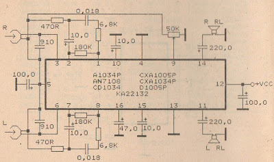
Schematic Audio Amplifier with IC AN7108


See this circuit below:

Datasheet IC AN7108
Vcc                = 1-6,6 V
Pout               = 2X 30 mW
RL                 = 32 Ohm
Ft                   = 20-20 Khz
Icco               = 14 mA
Package         = DIP-16
Manufactered = MATSUSHITA


Readmore → Schematic Audio Amplifier with IC AN7108

Monday, 26 December 2016

LM1875 20 Watt Audio Power Amplifier


20 Watt amplifier
20 Watts Power Amplifier circuit can be made ​​with an IC power amplifier LM1875. IC LM1875 is a single chip power amplifier from National. 20 watts audio amplifier with LM1875 is a low power amplifier with good quality to the room.


To assemble the amplifier 20 watts with IC LM1875 component is not needed much support. 20 watts power amplifier using LM1875 IC in this article using symmetrical power supply. The series of 20 watts audio power amplifier with IC LM1875 can be used as an experiment or first project for the reader, because it is simple and assembly of high success.

LM1875 | 20 Watt Audio Power Amplifier
Schematic Amplifier LM1875

LM1875 amplifier circuit with the above may result in the strengthening of the voltage up to 27dB for each channel (1 channel 1 IC). Strengthening the voltage can be changed by changing the feedback that is R5 R (on the circuit above using R 22K). But the tension reinforcement can not be less than 20 dB because it can cause oscillation. For the power supply or power supply 20 watts power amplifier rngakaian with lm1875 can use travo 2-3A with CT.

Readmore → LM1875 20 Watt Audio Power Amplifier

Sunday, 25 December 2016

1000Watt Audio Power Amplifier Blazer Circuit


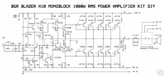
1000Watt Audio Power Amplifier Blazer Circuit
This is a audio power amplifier Blazer circuit provides up to 1000Watt . This fascinating routes several sensible bass and treble alive.
 Importantly ought to opt for Power offer supply, that has been fairly high voltage category 70Vdc GND -70V 10A is that the current low level.

The transistors are 2SC3858 (NPN) and 2SA1494 (PNP), and have high bandwidth, wonderful safe operating space, high linearity and high gain. Driver transistors are 2SC5200 (NPN) and 2SA1943 (PNP). All devices are rated at 230V, with the facility transistors having a 150W dissipation and also the drivers are 50W.

This circuit describes an amplifier, power offer and tests procedures that are all inherently dangerous. Nothing described during this article ought to even be thought-about unless you're totally experienced, grasp specifically what you're doing, and are willing to require full 100% responsibility for what you are doing. There are aspects of the look which will need analysis, fault-finding and/or modification.

Source: http://audio.circuitlab.org/2011/07/audio-1000watt-audio-power-amplifier.html#ixzz29oMliMOk


Readmore → 1000Watt Audio Power Amplifier Blazer Circuit

Saturday, 17 December 2016

TBA820 low power audio amplifier


TBA820 , KA2201 , LM820 , U820 amplifier
At this time amplifier circuit based on IC KA2201, TBA820M, LM820M, and U820. You can use all ic is the series under the scheme. This amplifier circuit has a very small output power or low at 2W. Required supply voltage from 3 volts to a maximum of 16 volts.


Below is a scheme of this power amplifier

TBA820 , KA2201 , LM820 , U820 rangkaian amplifier
Part List
R1 = 100K
R2 = 120R
R3 = 100R
C1 = 100nF
C2 = 100uF
C3 = 470uF
C4 = 220pF
C5 = 47uF
C6 = 100uF
IC = KA2201 , LM820M , TBA820M , U820M
Readmore → TBA820 low power audio amplifier

Monday, 12 December 2016

STK4050 Audio Amplifier with 200W Output


The project is based around the hybrid integrated circuit STK4050 manufactured by Sanyo to build a low noise mono audio amplifier with complete high quality. The project has a maximum output power of 200W while incorporating a volume control. The power supply used in the circuit is an on-board type and because of this, only a center tapped transformer is needed for the powering of the circuit. The sound has a very good quality and it can be proven when used in home theaters, in computers, and other audio equipments which can also be used as subwoofer amplifier. For thin-type audio sets, it can be considered as a compact package.

STK4050 Audio Amplifier with 200W Output

The heat generated in thin-type audio sets is being dispersed easily with a good heatsink design. There may be case where a shock noise may be encountered especially during switch ON and switch OFF. This can be reduced by providing a constant current circuit. The design of the circuit can be tailored for reducing occurrence of thermal shutdown, short circuit protection for loads, shock noise muting from external power supply. The load resistance should have 8 Ohms value with 55K Ohms input impedance.

Readmore → STK4050 Audio Amplifier with 200W Output