Showing posts with label Switching. Show all posts
Showing posts with label Switching. Show all posts
Thursday, 23 March 2017
12 Volt 2 A Switching Power Supply Circuit Diagram
This is a Simple 12 Volt / 2 A Switching Power Supply Circuit Diagram. The circuit 12 volt / 2 A switching power supply in the above scheme is not too complicated. At the output of this block provides a stable 12 V and maximum current 2A. Power supply units are quite compact and is suitable for debugging schemes, as well as a permanent resource for stationary devices, including power for the logic electronics for the home-made CNC machine tools.
Circuit Diagram

Transformer is available in the free market and avoids the hassle of having to self-winding. The diode bridge BR 1 of any given voltage and current of 2A. All other elements in the high part of the circuit are designed by the same voltage, taking into account the mains. The scheme of 12 volt / 2 A switching power supply operates from the high voltage network, to be observed when mounting accuracy and caution when using. It is desirable to block the finished board to “pack” in the body.

Thursday, 29 December 2016
Multi Switching System with automatic Time Delay Off MSTDO
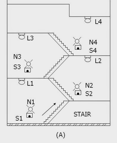
Energy conservation is the prime purpose of the design MSTDO. One particular application of the MSTDO is pressing of stairway lamps in a multi-storey building. When one desires to reach a certain floor level using the stairway, see figure below (A)
, he will return on the stairway lamps (L1,L2,L3…Ln) by pressing any one of the stairways push button switches (S1,S2,S3…N3). A sufficient time is allowed for him to reach his desire floor level destination. He need not turn off or push any switches to turn off the stairway lamp. The stairway lamp will be automatically turn off.
Readmore → Multi Switching System with automatic Time Delay Off MSTDO
(A) Push button switches and lamps installed in the stairway of a multi-storey building.
Control Operation
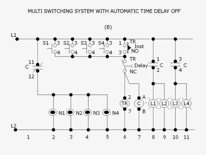
Referring to figure below (B), the neon lamps (N1,N2,N3…Nn) together with push button switches (S1,S2,S3…Sn) respectively installed in each stairway level are initially lighted on. The neon lamps are guide someone to reach on the stairway switches especially at night time. The stairway lamp (L1,L2,L3…Ln). Contact C (11-12)n will open to de-energize (light-off) condition.
Pressing any one of the stairway switches (S1,S2,S3…Sn) will energize the timer TR ( 2-7) and contactor C. Normally open instantaneous contact TR (1-3) will close to maintain the timer (2-7) and contactor C continuously energized even the press push button is stop. Contact C (1-2,3-4,5-6) will close to energized the stairway lamps L1,L2,L3…Ln) contact C (11-12) will open to de-energized the neon lamps (N1,N2,N3…Nn).
(B) Schematic diagram of the control circuit for “Multi Switching System with Automatic Time Delay Off”.
After several minute, the time sufficiently set to allow a person travel from the lowest to the highest floor level, the normally closed time delay contact TR (8-5) will open to de-energized the timer TR (2-7) and contactor C. Contacts C (1-2,3-4.5-6) will open to de-energized ,the stairway lamps (L1,L2,L3..Ln). Contact C ( 11-12) will close to its initial condition to energized the neon lamps (N1,N2,N3..Nn). Delay contact TR (8-5) will close and instantaneous contact TR (1-3) will open.If it is desire again to energize the stairway lamps (L1,L2,L3…Ln) one has to press again any one of the stairway way push button switches (S1,S2,S3…Sn).
Friday, 16 December 2016
Simple 2 Watt Small Switching Power Supply Circuit Diagram
In this small switching power supply, a Schmitt trigger oscillator is used to drive a switching transistor that supplies current to a small inductor. Energy is stored in the inductor while the transistor is on, and released into the load circuit when the transistor switches off.
2 Watt Small Switching Power Supply Circuit Diagram
2 Watt Small Switching Power Supply Circuit Diagram

The output voltage is dependent on the load resistance and is limited by a zener diode that stops the oscillator when the voltage reaches about 14 volts. Higher or lower voltages can be obtained by adjusting the voltage divider that feeds the zener diode. The efficiency is about 80% using a high Q inductor.
Wednesday, 7 December 2016
How to Repairing Switching Power Supply
Up to date power supply are renowned as "switching controller power supply." In most swapping supply, the 110 volt AC input is first rectified by two diodes and filtered by a pair of capacitors. This conceives two high- voltage causes; one positive and the other negative. A pair of transistors is then utilized to switch these high voltage supply over the primary winding of a transformer.
This switching activity is very fast. A usual switching pace is around 40,000 circuits per second or 40KHz. An integrated circuit is commonly utilised to control the transistors. This IC not only controls the pace at which the transistors are swapped, but furthermore controls the amount of time that each transistor is energized. The yield voltage of the power supply is very resolute by the "on" time of the transistors. If the transistors are hold on for a longer time span of time, the output voltage of the provide will rise, while shorter times smaller the yield voltage. This is renowned as "pulse-width modulation."
Power Supply

Subscribe to:
Posts (Atom)