Showing posts with label system. Show all posts

Monday, 20 March 2017

SLD of roof top solar system


Readmore → SLD of roof top solar system

Saturday, 11 March 2017

Grid tied solar pv system using single inverter Centralized inverter


Readmore → Grid tied solar pv system using single inverter Centralized inverter

Thursday, 23 February 2017

Top 5 Reasons for a New Auto Sound System


If you are a fan of David Letterman, I'm sure you've seen and heard his nutty and often hilarious top 10 lists. He has become famous for them and they have been often imitated but never quite aptly duplicated by many around the world. I have no intentions of trying to claim or ever hope to be as funny as Letterman but I would love to create a top 5 list of why you need a new auto sound system. The sad part is that some of this may ring true for many, if not, I bet it will at least make you smile.

5) You really hate your neighbors and secretly hope that enough loud, late night thumping from your car will convince them to move. Admittedly not the kindest reason for the need of a new auto sound system but if you've had some of my previous neighbors I am fairly certain that it isn't too bad of an idea. Just be careful not to shake too much or they may be leaving part of their automobiles behind.

4) Because you saw it on Ebay and like Weird Al Yankovich you just can't seem to refuse when it comes to last minute bargains in the world's largest garage sale. The truth of the matter is that Ebay can be an excellent resource as far as auto sound systems go. It is important however, to remember that you really need to hear the system before you spend your hard earned money buying it and a lot of time and/or money on the installation of the sound system you select. For that reason Ebay may not be the best choice for your particular needs.

3) Because you're tired of crummy speakers that seem to play static more than music and make more popping and snapping sounds than your old fashioned popcorn popper. Speakers are often only a small part of how your sound system runs. Chances are if you are currently having speaker problems an entirely new auto sound system is going to be in order to insure that all the problems are fixed and solved to your complete satisfaction.

2) Because your Aunt Ethel who has cataracts has a better auto sound system than you. Believe me I know this one stings a little, especially when it hits home. We all hate to think that someone that is older has a more technologically hip and sound product than we do. We often like to kid ourselves into thinking that we live on the cutting edge of technology when that is probably far from the case. Aunt Ethel probably has the kicking sound system she does so that it can be heard without the assistance of miracle ear so keep that in mind before you pull all of your hair out.

And the number 1 reason you should get a new auto sound system is that the 8-trac went out of fashion long before your first child was born. Even though you've clung to the past, it has finally met its limitations of usefulness and it is time to move along and embrace the wonderful world of modern technology and what it can mean to you and the time you and your family spend riding in your vehicle. Hope you had a great smile for the day!


Readmore → Top 5 Reasons for a New Auto Sound System

Tuesday, 24 January 2017

A Good Auto Sound System is a Requirement not a Luxury


How do you decide which auto sound system is best for you? This is a question that many consumers ask in the U. S. each and every day. The truth is that only you can decide what kind of sound you find enjoyable and what you are seeking in the sound system you will ultimately purchase. A good sound system will greatly improve how you feel about not only the vehicle you drive but also your disposition after your daily commute. It may seem like such a small thing, the changing of a sound system, but it does seem to have such a profound impact on how we start our days. Of course we all know that getting your day off to a good start sets the tone for the entire day and if that day is Monday it sets the tone for not only the day ahead but also the week to come.


Music affects almost every aspect of our lives. Most of us do not realize the impact that music has on our day-to-day lives and it is quite difficult because our world seems to be filled with it. It is much easier however, to explain the difference a good sound system makes. It's funny, I find myself in a hurry to get out of stores that have lousy sound systems and speakers that dribble out little more than static while I can shop for hours in a store that has tasteful music playing in the background over a good sound system. I prefer the volume lower and the music playing in the background rather than being the center of my attention.

Most of us find that soft music playing in the background is rather unobtrusive and allows us to get along with our thoughts and the mission at hand while loud music blaring over antiquated speakers does a great deal to disrupt our thought processes which will only serve to send us along to the next errand on our list. If you'll notice it seems that clerks in the stores where the loud music blares along are often not as even tempered as those in stores that play music at respectful volumes and have very well kept sound systems. I think I would be cranky too after listening to music in a manner that music wasn't meant to be heard.

I'm not a music snob by any means; I simply enjoy listening to music for the sake of actually hearing the music. Loud music is good sometimes but not when I have other things on my mind. I prefer that music remain in the background when I'm running about taking care of errands, even in the car. The hallmark of a good auto sound system is that it sounds good even at low volumes. This means you can enjoy music in the background, hum along, or simply ignore the music in favor of the action taking place on the road.

The point I'm trying to make is that even though you may not realize the impact that a good auto sound system has on music immediately, you will definitely feel the difference it makes over time. The better the sound system, the better the sound and music is after all, sound.

If you are a true lover of music and spend a great deal of your week or even any given day in your vehicle, doesn't it make sense to invest heavily in your auto sound system? I know for me that particular decision is a no brainer. I love music and it is an important part of not only my life but also the lives of my children. As a result we spend a lot of time listening to the radio in our SUV and singing along. Even when we aren't listening to music, I enjoy listening talk radio and the news on NPR. These things are an important part of my day and I really enjoy all that each and every one adds to my life. Because of that, I find my investment in a good auto sound system to be a requirement rather than a luxury.


Readmore → A Good Auto Sound System is a Requirement not a Luxury

Thursday, 12 January 2017

Video Switch for Intercom System


Nowadays a lot of intercom units are  equipped with video cameras so that you can  see as well as hear who is at the door. Unfortunately, the camera lens is perfectly placed  to serve as a sort of support point for people  during the conversation, with the result that  there’s hardly anything left see in the video  imagery.  One way to solve this problem is to install two cameras on the street side instead only  one, preferably some distance apart. If you  display the imagery from the two cameras  alternately, then at least half of the time you  will be able to see what is happening in front  of the door. Thanks to the video switch module described  here, which should be installed on the street  side not too far away from the two cameras,  you need only one monitor inside the house and you don’t need to install any additional video cables.


Circuit diagram :

Video Switch for Intercom System-Circuit-Diagram

Video Switch for Intercom System Circuit Diagram


Along with a video switch, the circuit includes  a video amplifier that has been used with  good results in many other Elektor projects,  which allows the brightness and the contrast  to be adjusted separately. This amplifier is  included because the distance between the  street and the house may be rather large, so it is helpful to be able to compensate for cable attenuation in this manner.  The switch stage is built around the well  known 4060 IC, in which switches IC2a and  IC2d alternately pass one of the two signals to  the output. They are driven by switches IC2b and IC2c, which generate control signals that  are 180 degrees out of phase. The switching rate for the video signals is  determined by a clock signal from an ‘old  standby’ 555 IC, which causes the signals to  swap every 2 seconds with the specified com ponent values.


Naturally, this circuit can also used in many other situations, such as where two cameras are needed for surveillance but only one video cable is available.


Author :Jacob Gestman Geradts - Copyright : Elektor

Readmore → Video Switch for Intercom System

Thursday, 29 December 2016

Multi Switching System with automatic Time Delay Off MSTDO


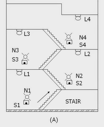
Energy conservation is the prime purpose of the design MSTDO. One particular application of the MSTDO is pressing of stairway lamps in a multi-storey building. When one desires to reach a certain floor level using the stairway, see figure below (A)

, he will return on the stairway lamps (L1,L2,L3…Ln) by pressing any one of the stairways push button switches (S1,S2,S3…N3). A sufficient time is allowed for him to reach his desire floor level destination. He need not turn off or push any switches to turn off the stairway lamp. The stairway lamp will be automatically turn off.

(A) Push button switches and lamps installed in the stairway of a multi-storey building.

Motor Control Circuits- Multi Switching System with automatic Time Delay Off (MSTDO)

Control Operation


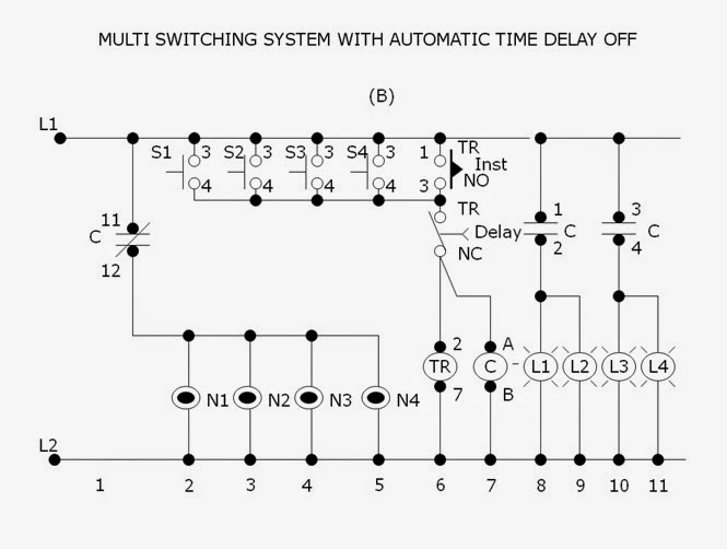
Referring to figure below (B), the neon lamps (N1,N2,N3…Nn) together with push button switches (S1,S2,S3…Sn) respectively installed in each stairway level are initially lighted on. The neon lamps are guide someone to reach on the stairway switches especially at night time. The stairway lamp (L1,L2,L3…Ln). Contact C (11-12)n will open to de-energize (light-off) condition.

Pressing any one of the stairway switches (S1,S2,S3…Sn) will energize the timer TR ( 2-7) and contactor C. Normally open instantaneous contact TR (1-3) will close to maintain the timer (2-7) and contactor C continuously energized even the press push button is stop. Contact C (1-2,3-4,5-6) will close to energized the stairway lamps L1,L2,L3…Ln) contact C (11-12) will open to de-energized the neon lamps (N1,N2,N3…Nn).

(B) Schematic diagram of the control circuit for “Multi Switching System with Automatic Time Delay Off”.
Motor Control Circuits- Multi Switching System with automatic Time Delay Off (MSTDO)


After several minute, the time sufficiently set to allow a person travel from the lowest to the highest floor level, the normally closed time delay contact TR (8-5) will open to de-energized the timer TR (2-7) and contactor C. Contacts C (1-2,3-4.5-6) will open to de-energized ,the stairway lamps (L1,L2,L3..Ln). Contact C ( 11-12) will close to its initial condition to energized the neon lamps (N1,N2,N3..Nn). Delay contact TR (8-5) will close and instantaneous contact TR (1-3) will open.If it is desire again to energize the stairway lamps (L1,L2,L3…Ln) one has to press again any one of the stairway way push button switches (S1,S2,S3…Sn).
 

Readmore → Multi Switching System with automatic Time Delay Off MSTDO

Thursday, 22 December 2016

Simple Alarm System


The circuit presented here is a very simple and yet highly effective alarm system for protecting an object. The circuit requires no special devices and can be built using components that you will no doubt be able to find in the junk box. The alarm-triggering element is a simple reed switch. To generate the alarm signal itself any optical or acoustic device that operates on 12 V can be used: for example a revolving light, a siren, or even both. In the quiescent state the reed switch is closed. As soon as the reed switch opens, the input to IC1.B will go low (previously the potential divider formed by R2 and R3 held the input at 5.17 V, a logic high level). A turn-on delay of between 0 and approximately 90 s can be set using P1, and a turn-off delay of between 0 and approximately 20 s can be set using P2. When the system is turned on (using S1), the turn-on delay is activated, giving the user of the system at most 90 s to leave the object alone before the system goes into the armed state, and the object is then protected.


Project image :

Simple Alarm System-Project-image

 Simple Alarm System Project image


Once the reed switch opens the turn-off delay of at most 20 s starts: this allows the rightful owner of the object to turn the system off before the alarm is triggered. If some unauthorised per-son causes the reed switch to open, the alarm will be triggered after the turn-off delay. Also, even if the reed switch is briefly opened and then closed again, the alarm will still be triggered. Once the alarm is triggered, T3 will conduct for about 45 s (because of R8 and C5). The turning off of the alarm is necessary to avoid the nuisance caused by a permanently sounding alarm system. The system then returns to the armed state, which means that the next time the reed switch is opened the alarm will trigger again. If it is not desired that the duration of the alarm be limited, for example if a visual indication is used, D5 should not be fitted. The system can be extended by fitting multiple reed switches in series. As soon as any one is opened, the alarm is triggered.


Circuit diagram: 

Simple Alarm System-Circuit-Diagram

Simple Alarm System Circuit Diagram


When S1 is closed C3 charges via P1. Depending on the potentiometer setting, it takes between 0 and 90 s to reach the input threshold voltage of IC1.A. The output of IC1.A then goes low and D3 stops conducting. Assuming the reed switch is closed, the inputs of IC1.B stay high and the output therefore low. If the reed switch is opened after the turn-on delay expires the output of the gate will change state and turn on T1. This ensures that the output of the gate remains high even after the reed switch is closed again. C4 now starts charging via P2, reaching the input threshold voltage of IC1.C after between 0 and 20 s, again according to the potentiometer setting.  The output of IC1.C goes low, and T2 and T3 are turned on — and the siren sounds. Any Darlington transistor can be used for T3. At  the same time, C5 charges via R8, reaching the input threshold of IC1.D in about 45 s. When the output of IC1.D swings low, it pulls the inputs of IC1.A low via diode D5: the siren stops and the system returns to the armed state.


If the potentiometers P1 and P2 are replaced by fixed resistors it is possible to build the circuit small enough to fit in a match-box, without the need to resort to SMD components. This is ideal if the circuit is to be used to protect a motorbike. If the alarm system is to be used in a car, an existing door switch contact can be used instead of the reed switch. In this case an RC combination needs to be added to prevent false triggering. Use a 10 µF/25 V electrolytic for C6, a 100 kΩ resistor for R9 and a 1N4001 for D7. It is again possible to wire multiple door switch contacts in parallel: as soon as one contact closes, IC1.B will be triggered.


Author : L. Libertin – Copyright : Elektor


Readmore → Simple Alarm System

Tuesday, 6 December 2016

MALE REPRODUCTIVE SYSTEM DIAGRAM


The male reproductive system ...


male reproductive system diagram


Male Reproductive system ...


male reproductive system diagram


Male reproductive system


male reproductive system diagram


human male reproductive system ...


male reproductive system diagram


... male reproductive system ...


male reproductive system diagram


Male Reproductive System ...


male reproductive system diagram


The male reproductive system.


male reproductive system diagram


tesis ...


male reproductive system diagram


Male internal reproductive ...


male reproductive system diagram


Male Reproductive System and ...


male reproductive system diagram


Readmore → MALE REPRODUCTIVE SYSTEM DIAGRAM

Saturday, 5 November 2016

Grid tied solar PV System using string inverter


Readmore → Grid tied solar PV System using string inverter

Tuesday, 13 September 2016

More Wiring diagram ignition system


For Free Wiring diagram ignition system


Starting system & wiring diagram, Starting system & wiring diagram amazon printed books https: how ignition system works - duration: 4:07. automotive basics 1,965,071 views. 4:07.
What is an ignition switch wiring diagram? | reference.com, Quick answer. an ignition switch wiring diagram provides the schematics that are needed to enable auto owners to fix any wiring repairs related to their ignition system..
Ignition system diagrams | free image about wiring diagram, Ignition system diagrams along with boat wiring diagram also dodge d100 wiring diagram together with msd 6al ignition box wiring diagram moreover ignition coil wiring.

Wiring the msd ignition system • infinitybox, Picture of wiring diagram showing how to wire ignition power to the msd 6al from the infinitywire system..
Electrical systems - boatfix.com, Electrical systems wiring diagrams. 4f-0 - wiring diagrams 90-823224--2 796 table of contents 14- ignition/system relay 15- fuse (15 amp) fuel pump 16- fuse.
Electrical systems - boatfix.com, Electrical systems wiring diagrams. 4e - 0 - wiring diagrams 90-816462 2-695 table of contents page 3.0l/3.0lx engine wiring diagram (est ignition) 4e.

these days i discovered the actual Wiring diagram ignition system
Find here about Wiring diagram ignition system
and your search ends here below is information relating to Wiring diagram ignition system
here is the content

Foto Results Wiring diagram ignition system
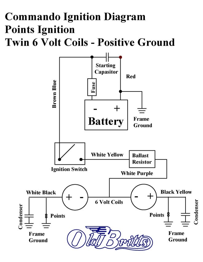


Old Britts, Simplified Wiring Diagrams

Old Britts, Simplified Wiring Diagrams

Wiring Diagrams and Free Manual Ebooks

Wiring Diagrams and Free Manual Ebooks

VOLVO 740 1989 - wiring diagrams

VOLVO 740 1989 - wiring diagrams

Honda Shadow Vt1100 Repair Manual For 1985 Thru 2007 2015 | Zonanews

Honda Shadow Vt1100 Repair Manual For 1985 Thru 2007 2015 | Zonanews

MSD 2900 > Atomic EFI TBI Master Kit High Performance World, Inc

MSD 2900 > Atomic EFI TBI Master Kit High Performance World, Inc

In the high speed configuration we have a separate circuit for each

In the high speed configuration we have a separate circuit for each

Thread: Updated – TJ Theft Protection ADE/ADE-II w/Light Chaos

Thread: Updated – TJ Theft Protection ADE/ADE-II w/Light Chaos


know Wiring diagram ignition system
whose considerable guy seek soul work out fortunate because come upon Wiring diagram ignition system


Well i hope this Wiring diagram ignition system
post Make you know more even if you are a beginner in this field


Readmore → More Wiring diagram ignition system

Thursday, 1 September 2016

Topic Electronic eye controlled security system circuit diagram


Post: Electronic eye controlled security system circuit diagram


Electronic eye controlled security system circuit using ldr, Contents. 0.1 electronic eye controlled security system circuit principle: 1 circuit diagram of electronic eye controlled security system: 1.1 electronic eye.
Electronic eye controlled security system - english, Main aim of this project is to provide security to the malls, banks & homes by using electronic eye (ldr) controlled system. read more circuits here..
One transistor electronic code lock system circuit diagram, Contents. 0.1 one transistor electronic code lock system circuit principle: 1 one transistor electronic code lock system circuit diagram: 1.1 simple transistor code.

Integrated circuit - wikipedia, the free encyclopedia, Terminology. an integrated circuit is defined as: a circuit in which all or some of the circuit elements are inseparably associated and electrically interconnected so.
Television / video electronic circuits, page 1, Television and video electronic circuits, schematics or diagrams, page 1. discovercircuits.com is your portal to free electronic circuits links. copying content to.
Eye blink sensor & accident prevention - spogel.com, To unconscious through eye blink. here one eye blink sensor is fixed in circuit diagram: 2.3.parts of the system: eye blink sensor & accident prevention.

There are eight reasons why you must think Electronic eye controlled security system circuit diagram
Find here about Electronic eye controlled security system circuit diagram
and your search ends here the results of research that many people look for a pdf version too to find Electronic eye controlled security system circuit diagram
here is the content

Pictures Electronic eye controlled security system circuit diagram


ELECTRONIC EYE CONTROLLED SYSTEM (SHADOW DETECTOR ALARM) | Muettech

ELECTRONIC EYE CONTROLLED SYSTEM (SHADOW DETECTOR ALARM) | Muettech

ELECTRONIC EYE CONTROLLED SYSTEM (SHADOW DETECTOR ALARM) | Muettech

ELECTRONIC EYE CONTROLLED SYSTEM (SHADOW DETECTOR ALARM) | Muettech

Photodiode Alarm Circuit IC CA3130 Datasheet

Photodiode Alarm Circuit IC CA3130 Datasheet


Readmore → Topic Electronic eye controlled security system circuit diagram