Wednesday, 22 March 2017
Car Anti Theft Wireless Alarm
This FM radio-controlled anti-theft alarm can be used with any vehicle having 6- to 12-volt DC supply system. The mini VHF, FM transmitter is fitted in the vehicle at night when it is parked in the car porch or car park. The receiver unit with CXA1019, a single IC-based FM radio module, which is freely available in the market at reasonable rate, is kept inside.
Receiver is tuned to the transmitter's frequency. When the transmitter is on and the signals are being received by FM radio receiver, no hissing noise is available at the output of receiver. Thus transistor T2 (BC548) does not conduct. This results in the relay driver transistor T3 getting its forward base bias via 10k resistor R5 and the relay gets energised.
When an intruder tries to drive the car and takes it a few metres away from the car porch, the radio link between the car (transmitter) and alarm (receiver) is broken. As a result FM radio module gene-rates hissing noise. Hissing AC signals are coupled to relay switching circuit via audio transformer. These AC signals are rectified and filtered by diode D1 and capacitor C8, and the resulting positive DC voltage provides a forward bias to transistor T2.
Thus transistor T2 conducts, and it pulls the base of relay driver transistor T3 to ground level. The relay thus gets de-activated and the alarm connected via N/C contacts of relay is switched on. If, by chance, the intruder finds out about the wireless alarm and disconnects the transmitter from battery, still remote alarm remains activated because in the absence of signal, the receiver continues to produce hissing noise at its output. So the burglar alarm is fool-proof and highly reliable. (Ed: You may have some problem catching the thief, though, if he decides to run away with your vehicle_in spite of the alarm!)
Copyright : EFY
Saturday, 4 February 2017
Cheap Bicycle Alarm Schematics Circuit
Auto Burglar Alarm Using 555 Timer ICs
Auto Burglar Alarm Circuit Diagram:

To set the alarm, open S2 (it is normally closed ) this will give you about 5 seconds to get out and close the door. The exit delay time is set by R1 and C1. If anyone opens the doors for more than two seconds the horn will sound until power is removed from the circuit. The 2 second time is set by R2 and C2. If you open the door, you must deactivate the alarm by closing S2.
Sunday, 15 January 2017
Build a Simple Home Alarm Circuit Using 555 ICs
Simple Home Alarm Circuit Diagram

The 74C14 contains 6 Schmitt Trigger gates and 4 of these gates (Schmitt Inverters) are used in this circuit.
The circuit consists of a number of "building blocks" and the first consists of two transistors in a very clever "bootstrap" arrangement. The first transistor is turned on via the 3M3 and 47k. The second transistor is not turned on and the output is HIGH.
A small signal from the electret microphone will consist of positive and negative excursions and the negative excursion will turn the first transistor OFF. This will turn the second transistor ON and the left lead of the 100n will be pulled towards the 0v rail. The 100n is uncharged and the right lead will also be pulled towards the 0v rail and the input of the 74C14 will see a LOW. This will make the output HIGH and turn on the BC547 transistor.
When the second transistor turns ON, it also pulls the 2u2 down and this removes the "turn-on" voltage to the first transistor. The two transistors remain in this state for a few seconds while the 2u2 discharges and the voltage on the base of the first transistor rises. When this happens, the two transistors change state and the 2u2 charges. When the circuit is waiting to detect audio, the 2u2 is charged via the 47k on the base of the first transistor and 47k collector resistor of the second transistor (plus the base-emitter voltage drop of the first transistor).
Simple Home Alarm Circuit Diagram A

To exit the property, the EXIT button is pressed and this puts a HIGH on pin 1 of the IC so that any signal from the electret mic is not passed to the siren. The EXIT delay is determined by the value of the 100u and 2M2. Normally-open and normally-closed switches will also send a LOW to trigger the siren.
Friday, 30 December 2016
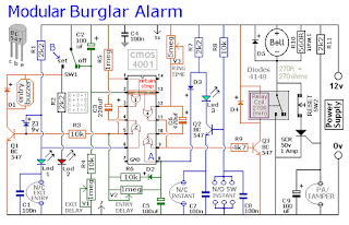
An Expandable Multi Zone Modular Burglar Alarm
Schematic Diagram

The Alarm is armed and disarmed by SW1. Before you move the switch to the "set" position - all the green LEDs should be lighting. You then have up to about a minute to leave the building. As you do so - the Buzzer will sound. It should stop sounding when you close the door behind you. This indicates that the Exit/Entry loop has been successfully restored within the time allowed.
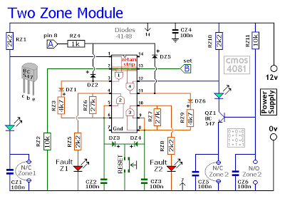
Two-Zone Expansion Module

The basic circuit will be satisfactory in many situations. However, if you have a large building to protect - it's much easier to find a fault - when the system is divided into zones - and the control panel can "remember" which zone has caused the activation.

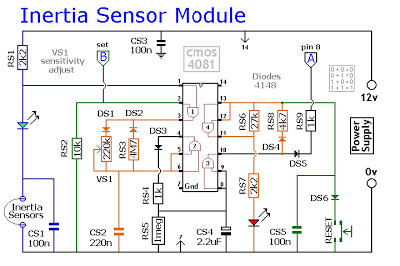
Inertia-Sensor Module
Thursday, 22 December 2016
Simple Alarm System
The circuit presented here is a very simple and yet highly effective alarm system for protecting an object. The circuit requires no special devices and can be built using components that you will no doubt be able to find in the junk box. The alarm-triggering element is a simple reed switch. To generate the alarm signal itself any optical or acoustic device that operates on 12 V can be used: for example a revolving light, a siren, or even both. In the quiescent state the reed switch is closed. As soon as the reed switch opens, the input to IC1.B will go low (previously the potential divider formed by R2 and R3 held the input at 5.17 V, a logic high level). A turn-on delay of between 0 and approximately 90 s can be set using P1, and a turn-off delay of between 0 and approximately 20 s can be set using P2. When the system is turned on (using S1), the turn-on delay is activated, giving the user of the system at most 90 s to leave the object alone before the system goes into the armed state, and the object is then protected.
Project image :
Simple Alarm System Project image
Once the reed switch opens the turn-off delay of at most 20 s starts: this allows the rightful owner of the object to turn the system off before the alarm is triggered. If some unauthorised per-son causes the reed switch to open, the alarm will be triggered after the turn-off delay. Also, even if the reed switch is briefly opened and then closed again, the alarm will still be triggered. Once the alarm is triggered, T3 will conduct for about 45 s (because of R8 and C5). The turning off of the alarm is necessary to avoid the nuisance caused by a permanently sounding alarm system. The system then returns to the armed state, which means that the next time the reed switch is opened the alarm will trigger again. If it is not desired that the duration of the alarm be limited, for example if a visual indication is used, D5 should not be fitted. The system can be extended by fitting multiple reed switches in series. As soon as any one is opened, the alarm is triggered.
Circuit diagram:
Simple Alarm System Circuit Diagram
When S1 is closed C3 charges via P1. Depending on the potentiometer setting, it takes between 0 and 90 s to reach the input threshold voltage of IC1.A. The output of IC1.A then goes low and D3 stops conducting. Assuming the reed switch is closed, the inputs of IC1.B stay high and the output therefore low. If the reed switch is opened after the turn-on delay expires the output of the gate will change state and turn on T1. This ensures that the output of the gate remains high even after the reed switch is closed again. C4 now starts charging via P2, reaching the input threshold voltage of IC1.C after between 0 and 20 s, again according to the potentiometer setting. The output of IC1.C goes low, and T2 and T3 are turned on — and the siren sounds. Any Darlington transistor can be used for T3. At the same time, C5 charges via R8, reaching the input threshold of IC1.D in about 45 s. When the output of IC1.D swings low, it pulls the inputs of IC1.A low via diode D5: the siren stops and the system returns to the armed state.
If the potentiometers P1 and P2 are replaced by fixed resistors it is possible to build the circuit small enough to fit in a match-box, without the need to resort to SMD components. This is ideal if the circuit is to be used to protect a motorbike. If the alarm system is to be used in a car, an existing door switch contact can be used instead of the reed switch. In this case an RC combination needs to be added to prevent false triggering. Use a 10 µF/25 V electrolytic for C6, a 100 kΩ resistor for R9 and a 1N4001 for D7. It is again possible to wire multiple door switch contacts in parallel: as soon as one contact closes, IC1.B will be triggered.
Author : L. Libertin – Copyright : Elektor
Monday, 21 November 2016
Motorcycle Alarm Circuit Diagram

Sourced by : Streampowers
Thursday, 10 November 2016
Burglar Alarm With Timed Shutoff Circuit Diagram