Showing posts with label an. Show all posts

Monday, 27 February 2017

An Electronic Watering Can Circuit Diagram


An Electronic Watering Can Circuit Diagram. Summertime is holiday time but who will be looking after your delicate houseplants while you are away? Caring for plants is very often a hit or miss affair, sometimes you under-water and other times you over-water. This design seeks to remove the doubt from plant care and keep them optimally watered. 

The principle of the circuit is simple: first the soil dampness is measured by passing a signal through two electrodes placed in the soil. The moisture content is inversely proportional to the measured resistance. When this measurement indicates it is too dry, the plants are given a predefined dose of water. This last part is important for the correct function of the automatic watering can because it takes a little while for the soil to absorb the water dose and for its resistance to fall. If the water were allowed to flow until the soil resistance drops then the plant would soon be flooded.

An Electronic Watering Can Circuit Diagram


An Electronic Watering Can-Circuit Diagram
An Electronic Watering Can Circuit Diagram

The circuit shows two 555 timer chips IC1 and IC2. IC1 is an astable multivibrator producing an ac coupled square wave at around 500 Hz for the measurement electrodes F and F1. An ac signal reduces electrode corrosion and also has less reaction with the growth-promoting chemistry of the plant. Current flowing between the electrodes produces a signal on resistor R13. The signal level is boosted and rectified by the voltage doubler produced by D2 and D3. When the voltage level on R13 is greater than round 1.5 V to 2.0 V transistor T2 will conduct and switch T3. Current flow through the soil is in the order of 10 µA. 

T2 and T3 remain conducting providing the soil is moist enough. The voltage level on pin 4 of IC2 will be zero and IC2 will be disabled. As the soil dries out the signal across R13 gets smaller until eventually T2 stops conducting and T3 is switched off. The voltage on pin 4 of IC2 rises to a ‘1’ and the chip is enabled. IC2 oscillates with an ‘on’ time of around 5 s and an ‘off’ time (adjustable via P2) of 10 to 20 s. This signal switches the water pump via T1. P1 allows adjustment of the minimum soil moisture content necessary before watering is triggered. 

The electrodes can be made from lengths of 1.5 mm2 solid copper wire with the insulation stripped off the last 1 cm. The electrodes should be pushed into the earth so that the tips are at roughly the same depth as the plant root ball. The distant between the electrodes is not critical; a few centimetres should be sufficient. The electrode tips can be tinned with solder to reduce any biological reaction with the copper surface. Stainless steel wire is a better alternative to copper, heat shrink sleeving can used to insulate the wire with the last 1 cm of the electrode left bare. Two additional electrodes (F1) are con nected in parallel to the soil probe electrodes (F). The F1 electrodes are for safety to ensure that the pump is turned off if for some reason water collects in the plant pot saucer. A second safety measure is a float switch fitted to the water reservoir tank. 

When the water level falls too low a floating magnet activates a reed switch and turns off the pump so that it is not damaged by running with a dry tank. Water to the plants can be routed through closed end plastic tubing (with an internal diameter of around 4 to 5 mm) to the plant pots. The number of 1 mm to 1.5 mm outlet holes in the pipe will control the dose of water supplied to each plant. The soil probes can only be inserted into one flowerpot so choose a plant with around average water consumption amongst your collection. Increasing or decreasing the number of holes in the water supply pipe will adjust water supply to the other plants depending on their needs. A 12 V water pump is a good choice for this application but if you use a mains driven pump it is essential to observe all the necessary safety precautions. 

Last but not least the electronic watering can is too good to be used just for holiday periods, it will ensure that your plants never suffer from the blight of over or under-watering again; provided of course you remember to keep the water reservoir topped up…

Author : Robert Edlinger

Readmore → An Electronic Watering Can Circuit Diagram

Friday, 30 December 2016

An Expandable Multi Zone Modular Burglar Alarm


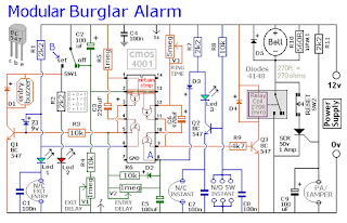
The Basic Alarm Circuit has an automatic Exit/Entry Zone - an Instant Alarm Zone that will accept both normally-closed and normally-open triggering devices - and an "Always On" 24-hour Personal Attack/Tamper Zone. By using the Expansion Modules - you can add as many extra alarm zones as you require.

Schematic Diagram

Expandable Multi-Zone Modular Burglar Alarm

The Alarm is armed and disarmed by SW1. Before you move the switch to the "set" position - all the green LEDs should be lighting. You then have up to about a minute to leave the building. As you do so - the Buzzer will sound. It should stop sounding when you close the door behind you. This indicates that the Exit/Entry loop has been successfully restored within the time allowed. 


When you re-enter the building - you have up to about a minute to move SW1 to the "off" position. If SW1 is not switched off in time - the relay will energize - and the main bell will ring. It will continue ringing for up to about 40 minutes. But it can be turned off at any time by SW1. 

The "Instant" zone has no Entry Delay. The moment one of its normally-open switches is closed - the main bell will ring. Similarly - the moment one of its normally-closed switches is opened - the main bell will ring. If you don't want to use normally-open switches - leave out R8, C8 and Q2 - and fit a link between Led 3 and C7.
The 24 Hour Personal Attack and Tamper protection is provided by the SCR/Thyristor. If one of the switches in the normally-closed loop is opened - current through R11 will trigger the SCR - and the main bell will ring. In this case the bell has no time limit. To reset the PA/Tamper zone - first restore the normally-closed loop - then press SW2 momentarily. This will interrupt the current and reset the SCR.

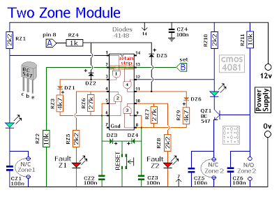
Two-Zone Expansion Module


Expandable Multi-Zone Modular Burglar Alarm

The basic circuit will be satisfactory in many situations. However, if you have a large building to protect - it's much easier to find a fault - when the system is divided into zones - and the control panel can "remember" which zone has caused the activation. 

The expansion modules are designed to do this. Although they will work with the existing instant zone - they are intended to replace it. When a zone is triggered - its red LED will light and remain lit - to indicate that the zone has been activated. 

The idea is that - once you've noted the zone in question - you then press the reset button and turn off the LED. The reset button simply turns off the LED. It doesn't reset the zone. The zone resets automatically when the trigger circuit is restored. If you're using more than one expansion module - they can all share a single reset button.

Expandable Multi-Zone Modular Burglar Alarm

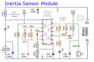
Inertia-Sensor Module


Readmore → An Expandable Multi Zone Modular Burglar Alarm

Saturday, 24 December 2016

Installing an under saddle pickup on an acoustic guitar


This beautiful guitar needs an under-saddle pickup. This is a kind of 4-step process, as follows:

1. Drill a 12mm (or 12.5mm) hole where the endpin used to be, to install the endpin jack.
2. Drill a hole through the bridge to allow the pickup wire to pass through.
3. Sand down the bottom of the old saddle, taking off the same amount as the height of the pickup that will now sit under it.
4. Solder the wire from the pickup to the endpin jack.


OK, let the adventure begin!

Firstly, before drilling a hole for the endpin jack, the old endpin needs to be removed. As this is tapered in shape, it should be easy to just yank it out. Get a good firm grip with your fingers and give it a tug. If you’re lucky, it’ll pull right out. In my case it did.


Now you’re left with a hole that is too small for the endpin jack. As you are not drilling a new hole, but rather expanding one that already exists, the traditional method is to use a reamer.

The problem with this method, however, is that a reamer leaves you with a tapered hole (unless you get a specialised one just for this job), so by the time you open the hole out to 12 mm at one end, it is still too small at the other end. To rectify this, you need to use a round file to file out the rest. I’ve done this before and it took a lot of time.

So instead, I decided to try a different approach this time. It just so happens I have a stepping drill bit whose largest diameter is exactly 12 mm. As it is a stepping drill bit, it behaves in a similar way to a reamer, in that it enlarges holes as it goes through, rather than making one huge 12mm hole in one go. This makes it a nice safe way to drill the endpin jack hole without having to worry about splitting or chipping wood. I wasn’t quite sure how this method was going to work out for me, but it worked perfectly. Note that this will only work if the largest diameter of your stepping drill bit is 12mm.


Most under-saddle pickups require you to drill a hole straight down through the bridge (under the saddle), but this particular pickup required the hole to be drilled at 45°. This was quite risky, as it was very difficult to avoid the bracing inside the guitar. If you are ever doing this, have a good feel inside the guitar to try to locate the closest bracing, in the hope that you can somehow avoid it (whatever you do, don’t have your hand in there while you are drilling the hole). Luckily in this case it was possible to avoid the brace by about the width of a human hair (no kidding).


The hole needs to be smoothed out with a small round needle file, so that there are no rough edges. For this particular type of pickup, it is also necessary to round off the 45° angle, so that the pickup/lead doesn't get a kink in it.


The pickup lead now needs to be fed through the hole and the pickup then placed in the saddle slot.


Now you need to sand the same amount off the bottom of the saddle as the height of the pickup. Use a Vernier caliper to measure the thickness of the pickup, then mark this on the bottom of the saddle. Simply rub the saddle against sandpaper taped to a very flat surface (it’s extremely important to get a flat surface on the bottom of the saddle, so do it right) until you have sanded off the correct amount.

The last thing you need to do before stringing up the guitar is to solder the pickup lead to the endpin jack. Make sure that before you do this, you slide any endpin jack covers, nuts, washers, etc., up the lead, as you won’t be able to do this once it’s soldered. You can slide these parts up the cable from inside the guitar, then pass the lead through the endpin jack hole to do the soldering outside the guitar. It’s a good idea to protect the finish on your guitar with rags or something while doing the soldering.

Here's what the endpin jack looks like before soldering:


Once soldered, push the endpin jack into the hole. Feed the washer and nut down the lead and onto the endpin jack (inside the guitar – yes, it’s fiddly). Tighten the endpin jack nut, making sure that it is nice and tight, as it will have a tendency to work loose otherwise. If there is some sort of endpin jack cover, fit this now.

Here's the endpin jack installed:


Now place the saddle in the saddle slot and string up the guitar.


Here's the finished product. She's a beauty, isn't she? Sounds great too.


Readmore → Installing an under saddle pickup on an acoustic guitar

Sunday, 27 November 2016

An Electronic Watering Can


Summertime is holiday time but who will be looking after your delicate houseplants while you are away? Caring for plants is very often a hit or miss affair, sometimes you under-water and other times you over-water. This design seeks to remove the doubt from plant care and keep them optimally watered.

The principle of the circuit is simple: first the soil dampness is measured by passing a signal through two electrodes placed in the soil. The moisture content is inversely proportional to the measured resistance. When this measurement indicates it is too dry, the plants are given a predefined dose of water. This last part is important for the correct function of the automatic watering can because it takes a little while for the soil to absorb the water dose and for its resistance to fall. If the water were allowed to flow until the soil resistance drops then the plant would soon be flooded.

Circuit diagram :

An Electronic Watering Can-Circuit Diagram

An Electronic Watering Can Circuit Diagram

The circuit shows two 555 timer chips IC1 and IC2. IC1 is an astable multivibrator producing an ac coupled square wave at around 500 Hz for the measurement electrodes F and F1. An ac signal reduces electrode corrosion and also has less reaction with the growth-promoting chemistry of the plant. Current flowing between the electrodes produces a signal on resistor R13. The signal level is boosted and rectified by the voltage doubler produced by D2 and D3. When the voltage level on R13 is greater than round 1.5 V to 2.0 V transistor T2 will conduct and switch T3. Current flow through the soil is in the order of 10 µA.

T2 and T3 remain conducting providing the soil is moist enough. The voltage level on pin 4 of IC2 will be zero and IC2 will be disabled. As the soil dries out the signal across R13 gets smaller until eventually T2 stops conducting and T3 is switched off. The voltage on pin 4 of IC2 rises to a ‘1’ and the chip is enabled. IC2 oscillates with an ‘on’ time of around 5 s and an ‘off’ time (adjustable via P2) of 10 to 20 s. This signal switches the water pump via T1. P1 allows adjustment of the minimum soil moisture content necessary before watering is triggered.

The electrodes can be made from lengths of 1.5 mm2 solid copper wire with the insulation stripped off the last 1 cm. The electrodes should be pushed into the earth so that the tips are at roughly the same depth as the plant root ball. The distant between the electrodes is not critical; a few centimetres should be sufficient. The electrode tips can be tinned with solder to reduce any biological reaction with the copper surface. Stainless steel wire is a better alternative to copper, heat shrink sleeving can used to insulate the wire with the last 1 cm of the electrode left bare. Two additional electrodes (F1) are con nected in parallel to the soil probe electrodes (F). The F1 electrodes are for safety to ensure that the pump is turned off if for some reason water collects in the plant pot saucer. A second safety measure is a float switch fitted to the water reservoir tank.

When the water level falls too low a floating magnet activates a reed switch and turns off the pump so that it is not damaged by running with a dry tank. Water to the plants can be routed through closed end plastic tubing (with an internal diameter of around 4 to 5 mm) to the plant pots. The number of 1 mm to 1.5 mm outlet holes in the pipe will control the dose of water supplied to each plant. The soil probes can only be inserted into one flowerpot so choose a plant with around average water consumption amongst your collection. Increasing or decreasing the number of holes in the water supply pipe will adjust water supply to the other plants depending on their needs. A 12 V water pump is a good choice for this application but if you use a mains driven pump it is essential to observe all the necessary safety precautions.

Last but not least the electronic watering can is too good to be used just for holiday periods, it will ensure that your plants never suffer from the blight of over or under-watering again; provided of course you remember to keep the water reservoir topped up…

Author : Robert Edlinger - Copyright : Elektor

Readmore → An Electronic Watering Can

Sunday, 20 November 2016

Build an AC Mains Short Circuit Protector Circuit Diagram


The simple short circuit and overload protector design presented here can be used for protecting valuable mains operated gadgets like amplifiers, TV sets, DVD players or any other similar appliance.Normally all sophisticated gadgets today incorporate an in built short circuit protector arrangement, yet still adding a more comprehensive external protection device could only benefit the connected system.

Moreover, for gadgets such as amplifiers which are home built this protection device could prove to be very effective and useful. Also for an hobbyist who prefers building electronic gadgets at home could be greatly benefited with the present idea.

The presented short circuit protector design works on a very basic principle and costs not more than a couple of dollars.

Let's learn the functioning details of the proposed circuit.

On applying power, the high current from the 220V input is dropped sufficiently by C1, rectified by D1 and filtered by C2 to feed the gate of the triac T1.

The triac conducts and switches ON the connected transformer primary thus switching ON the load which in this case is a power amplifier.

The transistor Q1 along with R1, R2 forms a current sensor stage.

R2 specifically is chosen such that it develops adequate voltage across itself at the specified dangerous high current threshold.

As usual the formula for determining R2 = 0.6/current(A)

As soon as the triggering voltage accumulates across R2, Q1 activates and sinks the gate voltage of the triac to ground making it switch off.

The regulation continues as long as the short or overload condition is not removed.

The above short circuit regulation ensures that the current level above the specified dangerous level is restricted safeguarding the precious devices associated with the connected amplifier.

If a latching feature is required for the above design, the emitter Q1 can be configured with an SCR and the SCR can be used for latching and switching off the triac.


AC Mains Short-Circuit Protector Circuit Diagram

AC Mains Short-Circuit Protector Circuit Diagram


Parts List


R1 = 100 ohms
R2 = see text
R3 = 1k
R4 = 10k
C1 = 0.33/400V
C2 = 1uf/250V
Q1 = BC547
Z1 = 12V/1 watt zener diode
T1 = BT136 or as per current rating
TR1 = As per load requirement specs.


Source By Swagatam

Readmore → Build an AC Mains Short Circuit Protector Circuit Diagram

Monday, 31 October 2016

Making a Solar Energy Powered an iPhone Battery Charger


The project was termed as Mighty Minty Boost as it was developed to function as iPod/iPhone charger with solar power. Aside from being small, it has a large battery capacity of 3.7V at 2000mAh and it accepts input power from 3.7V to 7V. As shown in the images below, it can become a compact USB power supply when the solar cell is removed after charging. The Velcro is used to secure the Mighty Minty Boost inside a backpack or messenger bag after unplugging the solar cell.

For faster charging, a larger solar cell can be attached to the bag. Enough power can be generated to fully charge an iPhone in about 5.5 hours and an iPod Touch in 4 hours using a slightly larger solar cell with 6V at 250mAh. The charger will automatically switch to trickle charging when the cell reaches full charge. The charging current is limited to 100mA when charging using the mini USB port and the charging is limited to 280mA when charging using the barrel plug jack

Hacks and Mods: iPhone Charger Powered Thru Solar Energy
.
The materials needed to build the charger include a small solar cell, Lithium Polymer battery charger, minty boost kit, adhesive backed Velcro, Altoids tin, connector/wire, and small double adhesive squares as shown in the images below. An input power that ranges from 3.7V to 7V maximum can be accepted by the single cell Lithium Polymer. In bright sunlight, the solar cell maxes out at approximately 5V at 100mA. A larger solar cell with 6V at 250mA can be used for faster charging.

Hacks and Mods: iPhone Charger Powered Thru Solar Energy

The images below show the assembly of minty boost kit where a JST connector is soldered to the minty boost PCB instead of connecting the battery holder in the kit. The minty boost circuit is allowed to connect to the Lithium Polymer battery charger circuit with this tiny connector. The minty boost is tested by connecting the battery pack and the charger circuit, the Lithium Polymer battery connects to the connector marked GND on the charger board and the minty boost connects to the connector marked SYS.

Hacks and Mods: iPhone Charger Powered Thru Solar Energy

To fit the charger, a notch is cut out of the other side of the Altoids tin and used double sided adhesive to secure the charging circuit to the bottom of the Altoids as shown below. The bottom of either one of the circuit boards should not touch the bottom of the Altoids tin while reconnecting the minty boost PCB and the battery to the charging circuit.

Hacks and Mods: iPhone Charger Powered Thru Solar Energy

Connecting or adding the solar cell can be done in different ways. Shortening the connector leads and plugging the barrel plug into the barrel jack on the charging circuit is one way. The other method is using another JST connector to replace the connector and plugging it into the third connector marked 5V on the charging circuit. Since there is no bog barrel plug sticking out of the side of the tin, using the second method is cleaner.

As shown in the photos below, some 2” Velcro was used to attach the solar cell to the top of the Altoids. To help protect the battery, a layer of clear packing tape was used for wrapping. N top of the two circuit boards, the battery pack is then set down. A red LED on the charger board will light up when the Mighty Minty Boost is set out in the bright sun. The iPod/iPhone/USB powered device can be connected once it is fully charged.

Hacks and Mods: iPhone Charger Powered Thru Solar Energy

Readmore → Making a Solar Energy Powered an iPhone Battery Charger