Showing posts with label Multi. Show all posts
Showing posts with label Multi. Show all posts
Friday, 30 December 2016
An Expandable Multi Zone Modular Burglar Alarm
The Basic Alarm Circuit has an automatic Exit/Entry Zone - an Instant Alarm Zone that will accept both normally-closed and normally-open triggering devices - and an "Always On" 24-hour Personal Attack/Tamper Zone. By using the Expansion Modules - you can add as many extra alarm zones as you require.
Schematic Diagram
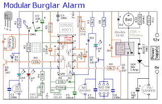
The Alarm is armed and disarmed by SW1. Before you move the switch to the "set" position - all the green LEDs should be lighting. You then have up to about a minute to leave the building. As you do so - the Buzzer will sound. It should stop sounding when you close the door behind you. This indicates that the Exit/Entry loop has been successfully restored within the time allowed.
When you re-enter the building - you have up to about a minute to move SW1 to the "off" position. If SW1 is not switched off in time - the relay will energize - and the main bell will ring. It will continue ringing for up to about 40 minutes. But it can be turned off at any time by SW1.
The "Instant" zone has no Entry Delay. The moment one of its normally-open switches is closed - the main bell will ring. Similarly - the moment one of its normally-closed switches is opened - the main bell will ring. If you don't want to use normally-open switches - leave out R8, C8 and Q2 - and fit a link between Led 3 and C7.
The 24 Hour Personal Attack and Tamper protection is provided by the SCR/Thyristor. If one of the switches in the normally-closed loop is opened - current through R11 will trigger the SCR - and the main bell will ring. In this case the bell has no time limit. To reset the PA/Tamper zone - first restore the normally-closed loop - then press SW2 momentarily. This will interrupt the current and reset the SCR.
Two-Zone Expansion Module
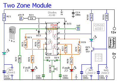
The basic circuit will be satisfactory in many situations. However, if you have a large building to protect - it's much easier to find a fault - when the system is divided into zones - and the control panel can "remember" which zone has caused the activation.
The expansion modules are designed to do this. Although they will work with the existing instant zone - they are intended to replace it. When a zone is triggered - its red LED will light and remain lit - to indicate that the zone has been activated.
The idea is that - once you've noted the zone in question - you then press the reset button and turn off the LED. The reset button simply turns off the LED. It doesn't reset the zone. The zone resets automatically when the trigger circuit is restored. If you're using more than one expansion module - they can all share a single reset button.
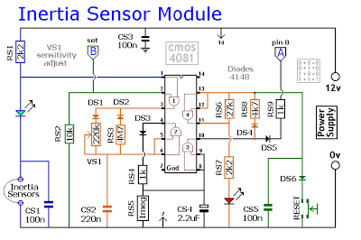
Inertia-Sensor Module

Thursday, 29 December 2016
Multi Switching System with automatic Time Delay Off MSTDO
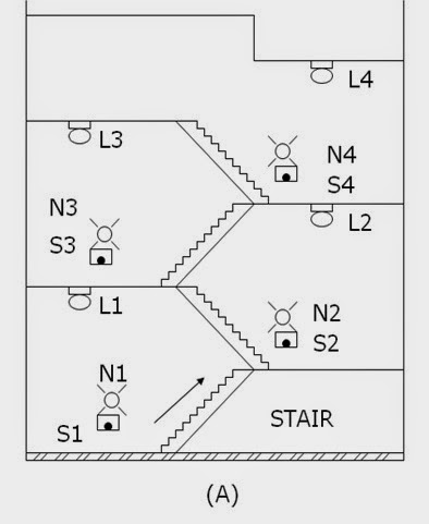
Energy conservation is the prime purpose of the design MSTDO. One particular application of the MSTDO is pressing of stairway lamps in a multi-storey building. When one desires to reach a certain floor level using the stairway, see figure below (A)
, he will return on the stairway lamps (L1,L2,L3…Ln) by pressing any one of the stairways push button switches (S1,S2,S3…N3). A sufficient time is allowed for him to reach his desire floor level destination. He need not turn off or push any switches to turn off the stairway lamp. The stairway lamp will be automatically turn off.
Readmore → Multi Switching System with automatic Time Delay Off MSTDO
(A) Push button switches and lamps installed in the stairway of a multi-storey building.
Control Operation
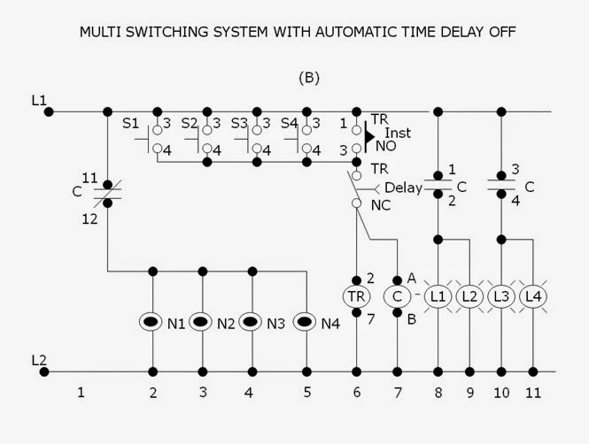
Referring to figure below (B), the neon lamps (N1,N2,N3…Nn) together with push button switches (S1,S2,S3…Sn) respectively installed in each stairway level are initially lighted on. The neon lamps are guide someone to reach on the stairway switches especially at night time. The stairway lamp (L1,L2,L3…Ln). Contact C (11-12)n will open to de-energize (light-off) condition.
Pressing any one of the stairway switches (S1,S2,S3…Sn) will energize the timer TR ( 2-7) and contactor C. Normally open instantaneous contact TR (1-3) will close to maintain the timer (2-7) and contactor C continuously energized even the press push button is stop. Contact C (1-2,3-4,5-6) will close to energized the stairway lamps L1,L2,L3…Ln) contact C (11-12) will open to de-energized the neon lamps (N1,N2,N3…Nn).
(B) Schematic diagram of the control circuit for “Multi Switching System with Automatic Time Delay Off”.
After several minute, the time sufficiently set to allow a person travel from the lowest to the highest floor level, the normally closed time delay contact TR (8-5) will open to de-energized the timer TR (2-7) and contactor C. Contacts C (1-2,3-4.5-6) will open to de-energized ,the stairway lamps (L1,L2,L3..Ln). Contact C ( 11-12) will close to its initial condition to energized the neon lamps (N1,N2,N3..Nn). Delay contact TR (8-5) will close and instantaneous contact TR (1-3) will open.If it is desire again to energize the stairway lamps (L1,L2,L3…Ln) one has to press again any one of the stairway way push button switches (S1,S2,S3…Sn).
Subscribe to:
Posts (Atom)