Showing posts with label Automatic. Show all posts

Saturday, 25 March 2017

Simple Automatic Curtain Opener Circuit Diagram


This is the Simple Automatic Curtain Opener Circuit Diagram. This circuit can be used with a timer clock to open and close curtains or (vertical) Venetian blinds. The curtain or blind is driven by an electric motor with a reduction gearbox fitted to the control mechanism of the curtain or blind. This circuit is ideal for giving your home an occupied appearance while you are away on holiday or for some other reason. In the author’s house, this arrangement has provided several years of trouble-free service on a number of windows fitted with Venetian blinds.

The original design was a simple relay circuit with push buttons for opening and closing and reed switches acting as limit switches. The mechanical drive is provided by a small DC motor with a reduction gearbox and pulley (all from Conrad Electronics). It was later modified to work automatically with a timer clock. The timer operates a small 230-VAC (or 120-VAC) relay with a changeover contact. Thanks to the two timers, the motor stops after a few seconds if one of the reed switches is missed due to a mechanical defect.


Automatic Curtain Opener Circuit Diagram

Automatic Curtain Opener Circuit Diagram

The circuit works as follows (see Figure 1). In the quiescent state, relays RE1–RE3 are de-energised and the motor is stopped. Open the blind:

When the timer clock applies power to the 230-V (120-V) relay RE3, the voltage at the junction of C1 and R1 goes high. IC1 (a 555) then receives a trigger pulse on pin 2, which causes its output (pin 3) to go High and energise RE1, which in turn causes the motor to start running. When the magnet reaches reed switch S1 (‘Open’), the 555 is reset. If the reed switch does not operate for some reason, the relay is de-energised anyhow when the monostable times out (time delay = 1.1 RC; approximately 5 seconds). Close the blind:

The timer clock removes power from RE3, which causes a trigger pulse to be applied to the other 555 timer (IC2) via R5 and C4. Now the motor starts running in the other direction. The rest of the operation is the same as described above for opening the blind. Diodes D2 and D5 prevent the outputs of the 555 ICs from being pulled negative when the relay is de-energised, which could otherwise cause the timer ICs to malfunction.

All components of the mechanical drive come from Conrad Electronics [2]: a motor with a reduction gearbox (type RB32, order number 221936) and a pulley (V-belt pulley, order number 238341) on the output shaft. An O-ring is fitted to the pulley to provide sufficient friction with the drive chain of the Venetian blind. The magnet for actuating the reed switches is a rod magnet with a hole in the middle (order number 503659), and the chain of the Venetian blind is fed through this hole.


                                                                                          Author : Ton Smits – Copyright : Elektor

Readmore → Simple Automatic Curtain Opener Circuit Diagram

Friday, 17 March 2017

Automatic Emergency Lamp Circuit


 This is an automatic emergency lamp with day light sensing, means it senses darkness/night and turns ON automatically. Similarly it senses day light and turns OFF automatically. A simple emergency lamp which does not require any special equipment; even a multimeter to assemble and use. Any individual who can do a good quality soldering must be able to build this circuit successfully.
This can be easily accommodated in the defunct two 6 watt tube National Emergency Lamp or any PL tube type emergency lamp. The difference will be in the working; it will work non stop for more than 8 hours. Deep discharge is taken care by the LED characteristic and over charge protection is taken care by the fixed voltage regulator.This uses a simple 3Pin fixed regulator which has a built in current limiting circuit.
Simple Emergency Light Circuit Diagram
Automatic Emergency Lamp Circuit
The only required adjustment is the preset which has to be set to ensure the LEDs just light up (it should be left at that position). The 5mm LDR is just mounted on top of the emergency light as shown in the photograph. LDR is used to avoid it lighting up during day time or when the room lights are ON. 2 LEDs are used in series; the dropping resistance is avoided and 2 LEDs light up with current that is required for a single LED,  by which energy is saved to a great extent.

This particular circuit has been kept so simple for people who has limited access to components or in other words this is an emergency light that you can build with minimum components. In addition to circuit diagram, He has shared photographs of the prototype he made in National emergency light and a PCB design.

Readmore → Automatic Emergency Lamp Circuit

Thursday, 2 March 2017

Automatic Night Light Feeds Directly From the AC Line


There are many approaches to the problem of activating a light when it becomes dark, and a recent Design Idea covers this topic (Reference 1). Some approaches require a dc power supply and an electromechanical relay, but a better approach involves feeding the device directly from the ac line, minimizing the number of components 

(Figure 1).


Figure 1. The photoresistor activates the TRIAC and the load when darkness falls.

The heart of the device is a light-sensitive cadmium-sulphide resistor, PR, with a resistance of approximately 200 kΩ in the dark and decreasing to a few kilohms in the light. PR and capacitor C1 form an ac-voltage divider. In daylight, the voltage across PR is too low to generate the required gate-trigger current to turn on bidirectional ac switch Q1, thus keeping the load – usually a lamp – off. When it becomes dark, PR’s resistance rises, resulting in an increase in the TRIAC’s gate current that triggers the TRIAC and lights the lamp.

The circuit uses inexpensive, off-the-shelf components, including the VT90N1 photoresistor; a 0.1-μF, 275V capacitor; and an L2004F61 TRIAC with a load current of 4A rms, a peak blocking voltage of 200V, and a gate-trigger current of 5 mA. The exact specifications of these components are not critical; you could use others instead.

Editor’s note:
Attributes worth mentioning include the fact that the capacitor introduces a phase shift, which places the peak of the gate voltage close to the zero crossing of the load’s sine wave for optimum turn-on timing. Another benefit is thermal hysteresis, which occurs due to the reduction of the required triggering voltage and current as the TRIAC warms up after the initial turn-on. 

Readmore → Automatic Night Light Feeds Directly From the AC Line

Wednesday, 1 March 2017

Automatic Battery Charger Circuit


Basically the circuit designed above have a very simple way of working, where the circuit is designed so that does not happen short circuit or short circuit between the voltage supply with batteries that will be in-charge.


Automatic Battery Charger Circuit

 It is true that if any one wants to try to direct mengghubungkan between supply with batteries then the batteries can be sure will be filled. But the current flowing through a charged battery can not be controlled and if the battery is full, the batteries will be damaged or worn out if it remains on the short circuit condition.

Working Principle Battery Charger

By the time we put an empty battery charging terminals, transistor Q1 will be activated immediately because the current flows through R1 and would trigger a transistor Q1 base. In this condition the flow that would fill the batteries mostly comes from the collector of Q1 is connected directly to the positive terminal of supply. Then during the charging process increases the battery voltage will increase the current flowing in Q2 base via 10 Kohm R5, VR1 and diode D2. VR1 is a component that is used as an initial calibration to determine the exact position in the planning process of switching circuit. For VR1 you can use a trimpot or potensio according to your taste. At the beginning of filling, arrange potensio at position D3 LED indicators on the condition of death, and the current flowing into the collector of Q1 is not too big and not too small.

If the battery is fully charged, the LED indicator will light up automatically because of an increase in voltage on the battery charge will cause the increase of current flowing at the base of transistor Q2 and will terminate the charging cycle due to transistor Q1 having a cut-off due to lack of base current. Why on condition Q1 base current will experience a shortage of this is because almost all the current flowing in R1 10 Kohm will switch to a diode D1 which is logically connected directly with ground experience due Q2 saturated.
.
Component List
1. Resistors: R1 (10 Kohm), R2 (680 ohms), R3 (100 Kohm), R5 (10 Kohm) and VR1 (Potensio / trimpot = 100 Kohm)
2. Diodes: D1 & D2 (IN4002) and D3 (Led)
3. Transistors: Q1 and Q2 (2N3904)
4. 9 volt power supply

Readmore → Automatic Battery Charger Circuit

Wednesday, 18 January 2017

Automatic Night Light using LDR


Here is the simple Automatic Night Light circuit using LDR.

Components Required:

1) Breadboard
2) 470 ohm resistor
3) 22 Kilo ohm resistor
4) LED (Any Color)
5) 15 Kilo ohm Light Dependent Resistor (LDR)
6) 3904 NPN Transistor
6) 9Volt Battery 

Procedure:
  • Connect the circuit as shown in the circuit diagram below.
  • During day time the brightness will be more, which lowers the resistance of the LDR.
  • Therefore the current is grounded, as current prefers only low resistance path.
  • Hence there is no base current to forward bias the 3904 NPN transistor and the LED remains OFF.
  • During night time the brightness goes down, which increases the resistance of the LDR.
  • Therefore the current will not be grounded and prefers a alternate path to flow.
  • Hence there is enough base current to forward bias the 3904 NPN Transistor and the LED glows.
Circuit Diagram:


Figure 1: Automatic Night Light using LDR Circuit simulation made in Multisim


Figure 2: Automatic Night Light using LDR

Readmore → Automatic Night Light using LDR

Thursday, 29 December 2016

Multi Switching System with automatic Time Delay Off MSTDO


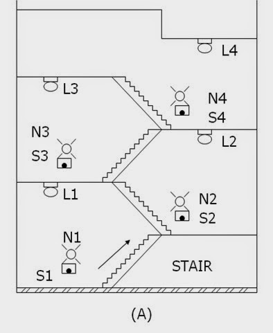
Energy conservation is the prime purpose of the design MSTDO. One particular application of the MSTDO is pressing of stairway lamps in a multi-storey building. When one desires to reach a certain floor level using the stairway, see figure below (A)

, he will return on the stairway lamps (L1,L2,L3…Ln) by pressing any one of the stairways push button switches (S1,S2,S3…N3). A sufficient time is allowed for him to reach his desire floor level destination. He need not turn off or push any switches to turn off the stairway lamp. The stairway lamp will be automatically turn off.

(A) Push button switches and lamps installed in the stairway of a multi-storey building.


Motor Control Circuits- Multi Switching System with automatic Time Delay Off (MSTDO)

Control Operation


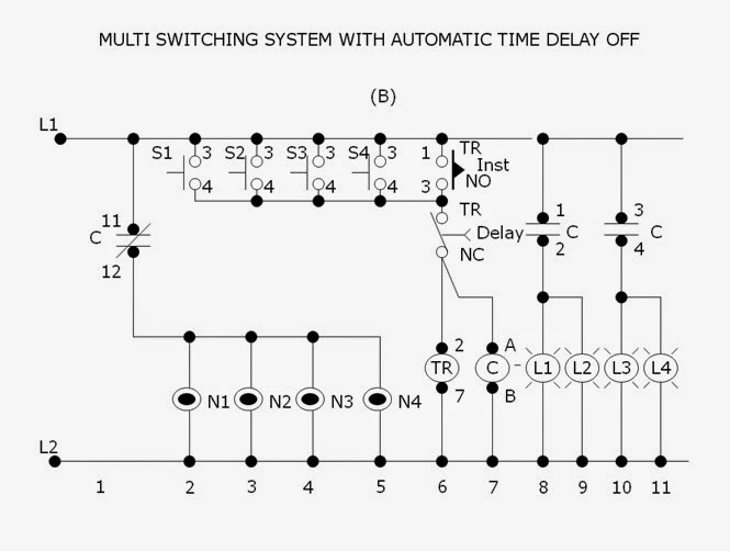
Referring to figure below (B), the neon lamps (N1,N2,N3…Nn) together with push button switches (S1,S2,S3…Sn) respectively installed in each stairway level are initially lighted on. The neon lamps are guide someone to reach on the stairway switches especially at night time. The stairway lamp (L1,L2,L3…Ln). Contact C (11-12)n will open to de-energize (light-off) condition.

Pressing any one of the stairway switches (S1,S2,S3…Sn) will energize the timer TR ( 2-7) and contactor C. Normally open instantaneous contact TR (1-3) will close to maintain the timer (2-7) and contactor C continuously energized even the press push button is stop. Contact C (1-2,3-4,5-6) will close to energized the stairway lamps L1,L2,L3…Ln) contact C (11-12) will open to de-energized the neon lamps (N1,N2,N3…Nn).

(B) Schematic diagram of the control circuit for “Multi Switching System with Automatic Time Delay Off”.

Motor Control Circuits- Multi Switching System with automatic Time Delay Off (MSTDO)


After several minute, the time sufficiently set to allow a person travel from the lowest to the highest floor level, the normally closed time delay contact TR (8-5) will open to de-energized the timer TR (2-7) and contactor C. Contacts C (1-2,3-4.5-6) will open to de-energized ,the stairway lamps (L1,L2,L3..Ln). Contact C ( 11-12) will close to its initial condition to energized the neon lamps (N1,N2,N3..Nn). Delay contact TR (8-5) will close and instantaneous contact TR (1-3) will open.If it is desire again to energize the stairway lamps (L1,L2,L3…Ln) one has to press again any one of the stairway way push button switches (S1,S2,S3…Sn).
 

Readmore → Multi Switching System with automatic Time Delay Off MSTDO

Friday, 4 November 2016

Automatic AC Power Switch Circuit Diagram


Electrical appliances accidentally left on  in (holiday) homes left unoccupied for a  short or a long period consume power  unnecessarily and can present a fire hazard. Everyone will be familiar with those  nagging thoughts, a few miles down the  road from the house: “Did I remember  to switch off the coffee machine? The  lights? The oven?” 

Automatic AC Power Switch Circuit Diagram


Automatic AC Power Switch-Circuit Diagram
Automatic AC Power Switch Circuit Diagram

Hotel rooms are often equipped with a  switch near the main door which enables the power supply to everything in  the room only when the plastic card (which  might contain a chip or have a magnetic strip  or a pattern of holes) that serves as the room  key is inserted. The circuit idea given here  to switch off lights and other appliances is  along the same lines. The solution is surprisingly simple. 

A reed contact is fitted to the frame of the main entrance door, and a matching magnet  is attached to the door itself such that when  the door is closed the reed contact is also  closed. To enable power to the house, press  S1 briefly. Relay RE1 will pull in and complete  the circuit for all the AC powered appliances in  the house. The relay will be held in even after  the button is released via the second relay contact and the reed contact (‘latching’ function). 

As soon as the main entrance door is  opened, the reed contact will also open.  This in turn releases the latch circuit and  consequently the relay drops out. The  various connected appliances will thus  automatically and inevitably be switched  off as soon as the house is left. The circuit is principally designed for  small holiday homes, where this mode  of operation is particularly practical. Of course, for any circuit that deals in AC  powerline voltages, we must mention  the following caution. 

Caution:
shock hazard! Construction and connection of this circuit  should only be carried out by suitably-qualified  personnel, and all applicable electrical safety  regulations must be observed. In particular, it  is essential to ensure that the relay chosen is  appropriate for use at domestic AC grid volt-ages and is suitably rated to carry the required  current.


Readmore → Automatic AC Power Switch Circuit Diagram