Showing posts with label off. Show all posts
Showing posts with label off. Show all posts
Thursday, 16 March 2017
Switch ON OFF Touch or with Push Button Circuit Diagram
Here we have three choices, with which we can make electronic switches that use our touch or pressing (push button). We thus exploit the very big resistance of entry, that present the gates CMOS. In the fig.1 we have two gates NAND or NOR (IC1), connected as R-S flip-flop. Just as we press the switch S1, the exit 3 it becomes [H], even it is maintained in this situation.
To change the situation, it should we press switch S2. Now exit 3, takes price (L), reversely exit 4 becomes (H). In order to we maintain the situation that we want, we can connect at parallel with the corresponding switch, a capacitor C=100nF. This entry will always drive the corresponding exit to logic (L), immediately afterwards the benefit of supply to the circuit.
Switch ON-OFF Touch or with Push Button Schematic
To change the situation, it should we press switch S2. Now exit 3, takes price (L), reversely exit 4 becomes (H). In order to we maintain the situation that we want, we can connect at parallel with the corresponding switch, a capacitor C=100nF. This entry will always drive the corresponding exit to logic (L), immediately afterwards the benefit of supply to the circuit.
Switch ON-OFF Touch or with Push Button Schematic

In the fig. 2, we have a circuit of inverter CMOS, in the entry of which is applied logic situation (H), from the resistance R, which the other end of, is in the supply. Exit 2 has situation (L).
When we press switch S2, in the entry of 3 IC2, we have situation (L), this it goes to the ground, the exit now becomes (H). This situations are maintained as long as we keep pressed switch S2 and they change immediately hardly the touch. If we want opposite logic operation then it will be supposed we connect the resistance R, in the ground and switch S2, in the supply. The same logic we will have if we replace gate IC2, with a gate NAND or NOR, as it appears in the fig. 3, the result is the himself.
Because the situation in the case of fig.1 and 3, does not remain constant and change when we pull our finger , in order to him we retain, it should we connect a J-K or D flip-flop as T, after the IC2 and IC3. Thus the flip-flop, will change situation, each time where we will touch the switch or will touch the contacts and him it will retain.
All the switches can be replaced with contacts, it is enough we replace also resistances R with the price of 10MΩ. The Resistances R when we use pressing switches can are, from 100KΩ until 1MΩ. Because when we use contacts instead of switches, the noise can turn on the gates of fig. 2 and 3, then can place a capacitor 100nF, parallel with the contacts.[via]

Thursday, 29 December 2016
Multi Switching System with automatic Time Delay Off MSTDO
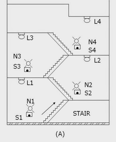
Energy conservation is the prime purpose of the design MSTDO. One particular application of the MSTDO is pressing of stairway lamps in a multi-storey building. When one desires to reach a certain floor level using the stairway, see figure below (A)
, he will return on the stairway lamps (L1,L2,L3…Ln) by pressing any one of the stairways push button switches (S1,S2,S3…N3). A sufficient time is allowed for him to reach his desire floor level destination. He need not turn off or push any switches to turn off the stairway lamp. The stairway lamp will be automatically turn off.
Readmore → Multi Switching System with automatic Time Delay Off MSTDO
(A) Push button switches and lamps installed in the stairway of a multi-storey building.
Control Operation
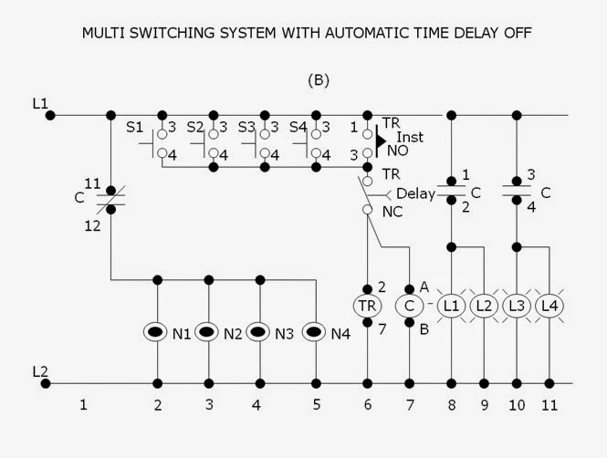
Referring to figure below (B), the neon lamps (N1,N2,N3…Nn) together with push button switches (S1,S2,S3…Sn) respectively installed in each stairway level are initially lighted on. The neon lamps are guide someone to reach on the stairway switches especially at night time. The stairway lamp (L1,L2,L3…Ln). Contact C (11-12)n will open to de-energize (light-off) condition.
Pressing any one of the stairway switches (S1,S2,S3…Sn) will energize the timer TR ( 2-7) and contactor C. Normally open instantaneous contact TR (1-3) will close to maintain the timer (2-7) and contactor C continuously energized even the press push button is stop. Contact C (1-2,3-4,5-6) will close to energized the stairway lamps L1,L2,L3…Ln) contact C (11-12) will open to de-energized the neon lamps (N1,N2,N3…Nn).
(B) Schematic diagram of the control circuit for “Multi Switching System with Automatic Time Delay Off”.
After several minute, the time sufficiently set to allow a person travel from the lowest to the highest floor level, the normally closed time delay contact TR (8-5) will open to de-energized the timer TR (2-7) and contactor C. Contacts C (1-2,3-4.5-6) will open to de-energized ,the stairway lamps (L1,L2,L3..Ln). Contact C ( 11-12) will close to its initial condition to energized the neon lamps (N1,N2,N3..Nn). Delay contact TR (8-5) will close and instantaneous contact TR (1-3) will open.If it is desire again to energize the stairway lamps (L1,L2,L3…Ln) one has to press again any one of the stairway way push button switches (S1,S2,S3…Sn).
Thursday, 24 November 2016
Off Hook Telephone Line Indicator
The circuit is designed to connect in parallel with the telephone line, to monitor and detect if any telephone in the same line is busy, with the indication of the LED and which is self-powered so that it does not provide any load on a telephone line.
Light Emitting Diode (LED) – a semiconductor diode that is commonly a source of light when electric current pass through it Metal Oxide Semiconductor Field Effect Transistor (MOSFET) – a device utilized for switching and amplification of signals BS108 – a 250 mA and 200 Volts small signal MOSFET designed for high voltage, high speed switching applications such as relay drivers, CMOS logic, line drivers, TTL or microprocessor to high voltage interface and high voltage display drivers Diode Bridge – also known as bridge rectifier which has four diodes arranged in a bridge configuration where the output voltage has the same polarity with either polarity of the input voltage 1N4007 – a general purpose plastic rectifier with reverse voltage from 50 Volts to 1000 Volts and forward current of 1.0 Ampere
When none of the telephone lines is in use or on-hook, the voltage across the line is around 48V. In this state, the gate of transistor Q2 is shorted to its source during the conduction of Q1. This causes the LED to be disabled while Q2 is turned OFF. When one telephone extension along the telephone line changes to off-hook or in use condition, a voltage drop from 5V to 15V is detected. This will in turn cause Q1 to turn OFF because of the very low voltage across the gate of Q1 which is equal to 6% of the line voltage. Transistor Q2 then will be biased at around half of the line voltage.
Off-Hook Telephone Line Indicator Circuit Diagram

The sudden line drop of voltage triggers Q2 to light up the LED that will give a sign that the line is in use. Using the same line, the circuit is unseen with other telephone devices. A current-limiting resistor is used to maintain the low current of LED1 while the local telephone line parameters dictate the variation of other component’s values. The power of the circuit is provided by the telephone line. Other voltage protection may be used with some reliable design in addition to the current-limiting resistor. This is important to avoid any grounding effects from conducting surfaces within the circuit.
To ensure that transistor Q1 is fully biased while the line is free or not in use where LED1 is OFF, a 500K ohm MOSFET trimmer is used for the desired adjustment. A MOSFET is a three-terminal semiconductor component with a conducting channel in its output and a built-in capacitor at its input. To increase the values of any of the two resistors connected to the gate of Q2, a 200V MOSFET can be used in the place of Q2 if BS108 is not available. However, plain transistors like the bipolar junction can be used but with lower values to allow greater currents to pass through the line that is not in use. The bridge rectifier comprising of four 1N4007 diodes are performing the conversion of AC input into DC output.
MOSFET can function in two ways. The first is known as depletion mode wherein the channel shows its maximum conductance in the absence of a voltage on the gate. The second way that the MOSFET can function is known as enhancement mode wherein the device is not conducting even in the absence of a voltage on the gate because no channel is produced. A channel is being created with the application of a voltage to the gate. To generate better conductivity, greater voltage to the gate is required.
MOSFET drivers are applied in electronic motor control for different types of motors. Also, they are specifically used with long duty cycles, high operating frequency above 200 KHZ, lower output power, and wide load variations. The largest application of MOSFETs are the switched mode power supplies and in battery charging applications. In transducer drivers for high power devices such as light bulbs and motors, large current output with a small input is provided by MOSFETs. Since they are more non-linear than BJTs while producing less distortion, they can be utilized with Hi-Fi amplifiers. In constructing integrated circuits, MOSFETs are very useful since they can be made very compact. Although MOSFETs can get damaged by static electricity at higher voltages, they still provide several advantages as compared to other transistors which include faster switching time than BJT, lower losses than BJT, very small switching current, and least effects of temperature.
This telephone line indicator does not only tell when a telephone line is in use if a plurality of telephones are all setup to the same telephone line, but also prevents interruptions during personal calls. Additionally, it can also help to prevent costly and unwanted disruption of modem calls and fax, it alerts a person when a call is done and the phone is free to use, and the LED light indicates the line is in use.
To avoid any injury, it is a prerequisite to take extra precautionary measures when connecting any circuit to the telephone lines, which can produce life-threatening voltages during normal operation. During a lightning storm, it is better to keep distance from telephone lines.. Legal aspects are imposed in different countries for connecting things to telephone lines. The circuit should be better built with a plug-in cord for easy removal in case of fault occurrences. Otherwise, it would be best to consult a licensed telephone operator.
Light Emitting Diode (LED) – a semiconductor diode that is commonly a source of light when electric current pass through it Metal Oxide Semiconductor Field Effect Transistor (MOSFET) – a device utilized for switching and amplification of signals BS108 – a 250 mA and 200 Volts small signal MOSFET designed for high voltage, high speed switching applications such as relay drivers, CMOS logic, line drivers, TTL or microprocessor to high voltage interface and high voltage display drivers Diode Bridge – also known as bridge rectifier which has four diodes arranged in a bridge configuration where the output voltage has the same polarity with either polarity of the input voltage 1N4007 – a general purpose plastic rectifier with reverse voltage from 50 Volts to 1000 Volts and forward current of 1.0 Ampere
When none of the telephone lines is in use or on-hook, the voltage across the line is around 48V. In this state, the gate of transistor Q2 is shorted to its source during the conduction of Q1. This causes the LED to be disabled while Q2 is turned OFF. When one telephone extension along the telephone line changes to off-hook or in use condition, a voltage drop from 5V to 15V is detected. This will in turn cause Q1 to turn OFF because of the very low voltage across the gate of Q1 which is equal to 6% of the line voltage. Transistor Q2 then will be biased at around half of the line voltage.
Off-Hook Telephone Line Indicator Circuit Diagram
The sudden line drop of voltage triggers Q2 to light up the LED that will give a sign that the line is in use. Using the same line, the circuit is unseen with other telephone devices. A current-limiting resistor is used to maintain the low current of LED1 while the local telephone line parameters dictate the variation of other component’s values. The power of the circuit is provided by the telephone line. Other voltage protection may be used with some reliable design in addition to the current-limiting resistor. This is important to avoid any grounding effects from conducting surfaces within the circuit.
To ensure that transistor Q1 is fully biased while the line is free or not in use where LED1 is OFF, a 500K ohm MOSFET trimmer is used for the desired adjustment. A MOSFET is a three-terminal semiconductor component with a conducting channel in its output and a built-in capacitor at its input. To increase the values of any of the two resistors connected to the gate of Q2, a 200V MOSFET can be used in the place of Q2 if BS108 is not available. However, plain transistors like the bipolar junction can be used but with lower values to allow greater currents to pass through the line that is not in use. The bridge rectifier comprising of four 1N4007 diodes are performing the conversion of AC input into DC output.
MOSFET can function in two ways. The first is known as depletion mode wherein the channel shows its maximum conductance in the absence of a voltage on the gate. The second way that the MOSFET can function is known as enhancement mode wherein the device is not conducting even in the absence of a voltage on the gate because no channel is produced. A channel is being created with the application of a voltage to the gate. To generate better conductivity, greater voltage to the gate is required.
MOSFET drivers are applied in electronic motor control for different types of motors. Also, they are specifically used with long duty cycles, high operating frequency above 200 KHZ, lower output power, and wide load variations. The largest application of MOSFETs are the switched mode power supplies and in battery charging applications. In transducer drivers for high power devices such as light bulbs and motors, large current output with a small input is provided by MOSFETs. Since they are more non-linear than BJTs while producing less distortion, they can be utilized with Hi-Fi amplifiers. In constructing integrated circuits, MOSFETs are very useful since they can be made very compact. Although MOSFETs can get damaged by static electricity at higher voltages, they still provide several advantages as compared to other transistors which include faster switching time than BJT, lower losses than BJT, very small switching current, and least effects of temperature.
This telephone line indicator does not only tell when a telephone line is in use if a plurality of telephones are all setup to the same telephone line, but also prevents interruptions during personal calls. Additionally, it can also help to prevent costly and unwanted disruption of modem calls and fax, it alerts a person when a call is done and the phone is free to use, and the LED light indicates the line is in use.
To avoid any injury, it is a prerequisite to take extra precautionary measures when connecting any circuit to the telephone lines, which can produce life-threatening voltages during normal operation. During a lightning storm, it is better to keep distance from telephone lines.. Legal aspects are imposed in different countries for connecting things to telephone lines. The circuit should be better built with a plug-in cord for easy removal in case of fault occurrences. Otherwise, it would be best to consult a licensed telephone operator.
Thursday, 22 September 2016
Battery charger circuit diagram auto cut off


images taken from various sources for illustration only Battery charger circuit diagram auto cut off
12v battery charger circuit with auto cut off - circuits, 12v battery charger circuit with auto cut off gallery of electronic circuits and projects, providing lot of diy circuit diagrams, robotics & microcontroller projects.
12v & 6v battery charger with auto cut off | circuit diagram, Here is a very simple automatic 12v and 6v battery charger circuit with auto cut off relay. the term auto cut off means that the circuit will automatically cut the.
Automatic battery charger circuit, 1. simple automatic battery charger circuit principle working. this is an automatic battery charger circuit, which normally producer will tell at battery as follows:.
Fast charger with auto cut off - electroschematics.com, This is the modified version of the fast charger circuit posted earlier. this circuit has auto cut off facility also. this high current charger can be used for the.
The simplist auto battery charger circuit using - youtube, The simplist auto battery charger circuit using 555(english version).
Battery charger circuits | circuitdiagram.org, A good designed circuit of a alkaline battery charger. the interesting thing of this circuit is that it uses a led that will show the charge of battery by blinking.
Hello there It's the specifics of Battery charger circuit diagram auto cut offThen This is the guide I know too lot user searching Battery charger circuit diagram auto cut off
The information avaliable here In this post I quoted from official sources Many sources of reference Battery charger circuit diagram auto cut off
With regards to this level of detail is useful to your
Subscribe to:
Posts (Atom)