Showing posts with label LED. Show all posts

Tuesday, 28 March 2017

Simple LED light Organ Circuit Diagram


This is a Simple LED light Organ Circuit Diagram. This is a fun circuit that can be at parties, for example. The four LEDs flash to the beat of the music. The light organ responds using a microphone to sound.T1 amplifies the signal from MIC. The sensitivity can be adjusted by P1. T4 controls the LEDs. 

These are preferably LED's with a high light intensity.MIC is a condenser microphone. The circuit can be powered by a 9 V battery.

 LED light Organ Circuit Diagram

 LED light Organ Circuit Diagram


The 4 Budget

This circuit costs about € 6.15.


Parts List

  •      R1 = 10 k
  •      R2 = 330 K?
  •      R3, R6, R13 = 100 k
  •      R4, R8, R11, R14 = 47 Ω
  •      R5, R9, R12 = 1.5 MΩ
  •      R7, R10 = 47 k
  •      P1 = 220 K?
  •      C1, C2, C3 = 100 nF
  •      C4 = 100 uF
  •      D1-D4 = LED
  •      T1, T2, T3 = BC547B
  •      T4 = BC557B
  •      MIC = microphone capsule

Readmore → Simple LED light Organ Circuit Diagram

Sunday, 26 March 2017

Simplest Transformerless LED Drivers


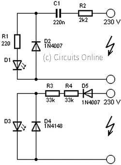
In this post we learn regarding three interesting transformerless power supply circuits for illuminating LEDs from mains that uses minimum number of components


Circuit 1


Simplest Transformerless LED Drivers


A capacitor must be having a rating of more than 200V and should be having dialectic of metallize polyester or poly poplin.

A resistor 1K is employed to limit the in rush current the resistor should be having the wattage value of more than 1Watt.

A diode is connected in anti-parallel to the LED. This diode limits the reverse voltage across the LED. The diode also provides the path for the negative half cycle as the LED is connected to a AC power source.

This particular circuit behaves like a constant current source of 15 to 20mA depending on LED voltage bias and supply line stability with a nominal 60Hz power supply frequency. The circuit 2 is an improvisation over circuit 1 and it enables to glow two LED’s at a time. This gives a color benefit also.

Putting two switches to the series part of individual LEDs can enable the viewer to have three colors.

In this transformerless circuit using the above formula the current can be manipulated by changing the capacitor value. Power LEDs can also be driven directly from AC power source.

Circuit2


Simplest Transformerless LED Drivers


The third circuit employs a zener diode of 5.6 V/1W. The zener diode serves dual purpose. Firstly it acts as a bias of the negative half of circuit like the diodes employed in circuit 1 and 2. Secondly, it acts as a voltage regulator for the LED driver circuit.

This circuit provides 5 Volts steady output with a 30mA current pumping facility. The 1000uF capacitor acts as a ripple suppressor and it allows a moderate ripple of 6% that is 300mV in this case. Employing the third circuit the use can expect better life of the LED. The current limiting capacitor used is 1.5uF at 200Volts.

The capacitor supplies the current to the driver as well it biases the zener to remain active during operation.

Please note that while using any LED it's datasheet should be studied beforehand. In general natural white LEDs, cool white LEDs, warm white LEDs all have a nominal bias voltage of 3.5V DC. But the activation starts at 2 to 2.4V DC.

The highest efficiency of the LED is achieved at 3.5V DC. Optimization of power supply is the highest priority in any LED driver circuit.

Circuit 3


Simplest Transformerless LED Drivers


If a constant voltage supply is provided it is to be notes that the power supply must have minimum ripple content.

The peak of the ripple shall also effect the performance of the LED so far as the junction temperature of the wafer is concerned. However a constant current source is a safest power supply alternative for a LED. A constant current source can achieved in many ways.

A variable power supply that is regulated by a current loop is the general trend. A capacitor in series is obviously the most economic constant current source so far as AC power supply is concerned.

Any fluctuation in the input power might result into the change in the current value,for this purpose,a regulator like 5.6 V zener is a safe practice.

While connecting the LED to the regulator circuit the power capacity of the regulator is to be kept in the mind along with the power requirement of the specific LED.

Readmore → Simplest Transformerless LED Drivers

Saturday, 25 March 2017

High Intensity Energy Efficient LED Light


Here is a rechargeable LED lamp that gives you bright light for a long duration of time as it consumes little power. The circuit presented here is compact, automatic, reliable, low-cost and easy to assemble.

The circuit comprises power supply, battery charging and switching sections. The power supply section takes power from 230V AC mains supply without using a transformer. Capacitor C1 is used as an AC voltage dropper, a well-known transformerless solution. This helps to make the circuit compact without generating heat, as capacitor C1 dissipates negligible power. Capacitor C1 also protects against fluctuations in mains.
Current required for the battery charging circuit is provided by capacitor C1. Capacitor C1 discharges through resistor R1 when the circuit is disconnected from the mains voltage. This helps to prevent a fatal shock due to any voltage remaining in the input terminals. Capacitor C1 must be rated at least 440V AC, with mains application class X2.


The AC mains voltage after capacitor C1 is given to bridge rectifier diodes D1 through D4 to convert alternating current into direct current and filtered by capacitor C2. The voltage from point B+ is given to positive terminal of the battery (BATT), anodes of LEDs (LED2 through LED21) and transistor base-bias resistor R3 through slide switch S1. The circuit is operated in three modes (AC/charge, off and batt) by using three-position switch S1.


When switch S1 is in middle position, the circuit is off. When S1 is towards right, white LEDs glow by drawing power from 4V battery. When S1 is towards left, the circuit connects to AC mains and battery starts charging. The presence of AC mains voltage and battery charging is indicated by LED1. White LEDs remain off if AC mains supply is available and glow in the absence of AC mains.

When switch S1 is towards left position and AC mains is available, the battery charges through diode D6 and the white LEDs don’t glow. The negative DC path through diode D5 makes the transistor cut-off, preventing the battery current from LEDs to the negative terminal through the transistor. Thus the white LEDs don’t glow.

On the other hand, if AC mains is not available, charging stops and the base of transistor SS8050 gets positive voltage from the battery through slide switch S1 and resistor R3. The transistor conducts and the current flows from the battery’s positive terminal to the negative terminal of the battery through the
LEDs (LED2 through LED21), collector to emitter of transistor T1 and switch S1. Thus the white LEDs glow.


When the switch is in ‘batt’ position, the white LEDs (LED2 through LED21) get the supply directly from 4V battery through switch S1 and therefore all the white LEDs glow.


Assemble the circuit on a general purpose PCB and enclose in a suitable cabinet. Fix the mains power cord on the back of the cabinet and slide switch
and LEDs on the front side.


Schematic:
LED Lamp
Component Required:
R1,                   470K ohm
R2,                   270 ohm
R3,R4,              470 ohm
C1,                   1uF / 440V Maylar
C2,                   220uF/ 16V electrolyte
D1-D6,              1N4007
T1,                   SS8050
S1,                   Sliding switch
LED1,                Red LED
LED2-LED21,      Bright white LEDs
BATT,                4V, 0.8AH
Readmore → High Intensity Energy Efficient LED Light

Wednesday, 8 March 2017

230Volt LED Circuit


This is a circuit that is used to menhidupkan LED with voltage 230Volt, 230Volt it so that the voltage must be lowered in accordance with the needs of the LED itself. To lower it even necessary circuit as below.

230Volt LED Circuit


Readmore → 230Volt LED Circuit

Saturday, 4 March 2017

DRIVING A BI COLOURED LED USING NE555


Readmore → DRIVING A BI COLOURED LED USING NE555

Monday, 13 February 2017

UP DOWN FADING LED CIRCUIT USING NE555


Readmore → UP DOWN FADING LED CIRCUIT USING NE555

Thursday, 9 February 2017

Simple Strip LED Lamp Circuit Diagram


Strip LEDs are available in different colours powered by direct current (DC) source. These LEDs are available as surface mount devices with current limiting resistors. Usually there are 300 LEDs in a 5-metre strip. The strip can be cut into pieces so that the bits having three or four LEDs can be used with 12V DC source. The circuit given here uses the strip LEDs to make an automatic white LED lighting source. The circuit is powered by a capacitor power supply connected to AC mains. Capacitor C1 drops the 230V AC, which is further rectified by the bridge rectifier module and is made ripple-free by C2. Zener diode (ZD1) provides 12V DC to the comparator circuit.

Simple Strip LED Lamp Circuit Diagram


Strip LED Lamp

Resistor R1 is important in the power supply as it provides discharge path to the voltage stored in capacitor C1 after the circuit is unplugged from mains. The automatic working of the circuit is based on the light-sensing property of the light-dependent resistor (LDR). Operational amplifier CA3140 (IC1) is used as a comparator with two potential dividers in its inverting and non-inverting inputs. LDR1 and resistor R3 form one potential divider that provides a variable voltage at the inverting input pin 2 of IC1. Second potential divider comprises resistors R4 and R5, which provide half of the supply voltage (6V) to the non-inverting pin 3 of IC1. The output of IC1 depends on voltage level at inverting input pin 2 of IC1 as explained below.

In daylight, LDR1 has low resistance and the voltage at inverting input (pin 2) of IC1 is more than that of non-inverting input (pin 3). This makes IC1 output low, which drives transistor T1 into cut-off condition and strip LEDs do not glow. However, at night the light incident on LDR1 is low and its resistance is high. The voltage at inverting input of the comparator decreases, making it lower than the voltage at non-inverting input. This makes IC1 output high. Transistor T1 goes into saturation, thus connecting cathodes of LEDs to ground. All the LEDs in the strip turn on and remain that way till morning.

Assemble the circuit on a general-purpose PCB and enclose it in a suitable shock-proof case. Strip LEDs are available in ribbon-shaped form. Use 5cm bits (two bits) having three LEDs each. The strip can be cut at supply-contact points. Strip LEDs are arranged on a flexible belt with double-sided adhesive on the back side, so it can be glued to any surface. Connect the LED strip in the circuit with correct polarity. EFY note. Since the circuit uses 230V AC, there is a risk of electrical shock. Do not touch or troubleshoot when the circuit is plugged in. Before connecting the circuit to the power supply section, test it using 12V DC from a battery or DC power supply. 


SOURCE : circuitsstream

Readmore → Simple Strip LED Lamp Circuit Diagram

Sunday, 5 February 2017

Flasher with LED high Intensity Circuit Diagram


This Flasher with LED high Intensity Circuit Diagram was designed as a flasher warning and was originally mounted on a bicycle. White LEDs are only recommended if the circuit is used as a bicycle front light and red LEDs only when used as a taillight. During the day, the two solar cells carry two 1.6 V AA batteries. In the darkness, the cell voltage disappears solar energy and batteries are automatically diverted to the circuit. The frequency of blinking (flashing) is about one per second.

Flasher with LED high Intensity Circuit Diagram

Flasher with LED high Intensity Circuit Diagram

If you liked this article,Take a few Seconds to Share this and leave comments

Readmore → Flasher with LED high Intensity Circuit Diagram

Current Controlled Boost LED Driver and Black Soldermasks


The MAX16834 is a neat little chip (it's not the only one, there are plenty of others out there) that allows high efficiency designs for LED string driving. It provides a platform for a Buck or Boost converter design, as well as brightness adjustment via analog/PWM input pins, as well as a fault output (in case of open/short circuits for example) and also diverse other functionalities that can be quite useful. [ ]


Readmore → Current Controlled Boost LED Driver and Black Soldermasks

Tuesday, 24 January 2017

Solar LED Lantern Circuit Diagram


This solar LED lantern can be used as an emergency light. Its 6V battery can be charged either from 230V, 50Hz AC mains or a 12V, 10W solar panel. Two LED indicators have been provided—red LED (LED1) indicates battery charging and green LED (LED2) indicates fully-charged battery.


Solar LED Lantern Circuit Diagram


You can choose to charge the battery either from the mains power or the solar panel by using the single-pole, double-throw (SPDT) switch. Capacitor C1 (1000µF, 35V) removes ripples from the power supply and regulator IC LM7809 (IC1) provides regulated 9V DC to the emitter of pnp transistor T1 (TIP127/BD140) and pin 7 of op-amp IC CA3140 (IC2), which is configured in comparator mode.

The reference voltage of 6.3V at pin 2 of IC2 is obtained through the combination of resistor R7 (1-kilo-ohm) and zener diode ZD1 (6.3V). The comparator controls charging of the battery. Pin 3 of IC2 is connected to the positive terminal of the battery to be charged through resistor R5. When the battery is fully charged, it stops charging and the green LED (LED2) glows to indicate the full-charge status.

When the battery voltage is low, diode D1 (1N4007) forward-biases and the battery connects (through resistor R3) to the collector of T1 for charging (indicated by the glowing of red LED1). Three high-wattage white LEDs (LED3 through LED5), such as KLHP3433 from Kwality Photonics, are used for lighting. These are switched on using switch S3.

Readmore → Solar LED Lantern Circuit Diagram

Wednesday, 18 January 2017

Capacitor Discharging pattern using LED


Components Required:

1) Breadboard
2) 470 ohm resistor
3) 1000uf Capacitor
4) LED (Any Color)
5) 9Volt Battery 
6) Push Button Normally Open (PBNO)
7) Digital Multimeter 

Procedure:
  • Connect the circuit as shown in the circuit diagram below.
  • The PBNO switch is normally open and the circuit is not closed therefore the capacitor will not be charged and the LED will not glow.
  • Once the push button is pressed the charge flows from the battery and charges the capacitors and glows the LED.
  • Even after the push button is released the LED glows for a period of 470 ms based on the RC time constant calculated for 1000uf capacitor and 470 ohm resistor. 
  • Resistance value multiplied by the capacitance value gives the RC time constant.
  • This is because when the push button is pressed the capacitor is charged and even after when the push button is released the charge stored in the capacitor closes the circuit and gets discharged through the closed circuit.
  • Charge stored in the capacitor discharges exponentially which can be visually noticed by the brightness of the LED which becomes dimmer when discharging.
  • To observe discharging pattern clearly use large resistance values say 10Kilo ohm for the same capacitance value which results in larger RC time constant for nearly 10 sec.
Circuit Diagram:


Figure 1: Capacitor Discharging pattern using LED Circuit simulation made in Multisim


Figure 2:  Capacitor Discharging pattern using LED (Push button open)


Figure 3:  Capacitor Discharging pattern using LED (Push button closed)

Readmore → Capacitor Discharging pattern using LED

USB LED Night Light Circuit Diagram


A typical USB LED bulb shown in Fig. 1 is a 5V, 5W USB-powered solid-state lamp. At the heart of this light bulb is a circular aluminium PCB made with a bunch of 5730 SMD super-bright LEDs. Typical working voltage of a single 5730 SMD LED is in the range of 2.9V to 3.4V, and its current consumption is about 150mA. Fig. 2 shows some details of SMD LEDs used in the USB LED bulb. 


This gizmo inspired me to design a distinct USB LED night light with battery backup. Read More Click He


Readmore → USB LED Night Light Circuit Diagram

Wednesday, 11 January 2017

LED Photo sensor


It is not always necessary to use special photoresistors or phototransistors to make light-sensitive switches. Although it is not well known, normal visible-light and infrared LEDs will also work. A voltage that depends on the intensity of the natural or artificial illumination falling on the LED can be taken from the anode of the LED. This behaviour can be easily verified by connecting a DVM or oscilloscope directly to the two leads of the LED.
Circuit Diagram:
LED Photosensor-Circuit Diagram
LED Photosensor Circuit Diagram
Since the load on the photoelectric potential should be kept as small as possible, a JFET is used here as a buffer. The type used is not critical; similar transistors should work equally well. The buffered voltage is fed to the inverting input of comparator IC1. The threshold voltage can be adjusted to meet the desires of the user by means of the potentiometer. A pull-up resistor is connected to the com-parator output, since the LM393 has an open-collector out-put. The supply voltage may be chosen anywhere in the range of 5 to 9 V.


Readmore → LED Photo sensor

Saturday, 24 December 2016

Battery Charger Small LED Lamp based Solar Cell Photovoltaic


Battery Charger using Photo Voltaic


This is the circuit diagram of rechargable battery charger which use solar cell / photovoltaic as the DC source. This circuit works to charge 3 types of rechargable batteries that are lead acid, Ni-Cd and Li-ion. The lead-acid batteries are generally utilized in emergency lamps and UPS. The photovoltaic module or solar cell explained in this post is capable of producing a power of 5 watts. At full sunlight, the solar cell outputs 16.5V. It can deliver a current of 300-350 mA.

How the circuit works?
The working of the circuit is quite simple. The output of the solar panel is fed via diode 1N5402 (D1), which acts as a polarity guard and protects the solar panel. An ammeter is connected in series between diode D1 and fuse to measure the current flowing during charging of the batteries. As shown in Image #1, we have used an analogue multimeter in 500mA range. Diode D2 is used for protection against reverse polarity in case of wrong connection of the lead-acid battery. When you connect wrong polarity, the fuse will blow up.
For charging a lead-acid battery, shift switch S1 to ‘on’ position and use connector ‘A.’ After you connect the battery, charging starts from the solar panel via diode D1, multimeter and fuse. Note that pulsating DC is the best for charging lead-acid batteries. If you use this circuit for charging a lead-acid battery, replace it with a normal pulsating DC charger once a week. Keep checking the water level of the leadacid battery. Pure DC voltage normally leads to deposition of sulphur on the plates of lead-acid batteries.

For charging Ni-Cd cells, shift switches S1 and S3 to ‘on’ position and use connector ‘B.’ Regulator IC 7806 (IC1) is wired as a constantcurrent source and its output is taken from the middle terminal (normally grounded). Using this circuit, a constant current goes to Ni-Cd cell for charging. A total of four 1.2V cells are used here. Resistor R2 limits the charging current.
For charging Li-ion battery (used in mobile phones), shift switches S1 and S2 to ‘on’ position and use connector ‘C.’ Regulator IC 7805 (IC2) provides 5V for charging the Li-ion battery. Using this circuit, you can charge a 3.6V Li-ion cell very easily. Resistor R3 limits the charging current. Image #2 shows the circuit for a small LED-based lamp. It is simple and lowcost. Six 10mm white LEDs (LED2 through LED7) are used here. Just connect them in parallel and drive directly by a 3.6V DC source. You can use either pencil-type Ni-Cd batteries or rechargeable batteries as the power source.
Assemble the circuit on a general purpose PCB and enclose in a small box. Mount RCA socket on the front panel of the box and wire RCA plug with cable for connecting the battery and LED based lamp to the charger.
With this circuit, you can save on your electricity bills by switching to alternative sources of power.


Readmore → Battery Charger Small LED Lamp based Solar Cell Photovoltaic

Saturday, 19 November 2016

LED Lighting For Consumer Unit Cupboard


The consumer unit (or ‘electricity meter’) cupboard in some older houses is a badly lit place. If the bell transformer is also located in this cupboard, it may be used to provide emergency lighting by two high-current LEDs. These diodes are powered via a small circuit that switches over to four NiCd batteries when the mains fails. The output voltage of the bell transformer is rectified by bridge B1 and buffered by capacitor C1. The batteries are charged continuously with a current of about 7.5 mA via diode D1 and resistor R2. The base of transistor T1 is high via R3, so that the transistor is cut off. When the mains voltage fails, C1 is discharged via R1; when the potential across it has dropped to a given value, the battery voltage switches on T1 via R3 and R1, provided switch S1 is closed. When T1 is on, a current of some 20 mA flows through diodes D4 and D5. The light from these LEDs is sufficient to enable the defect fuse or the tripped circuit breaker to be located.

Circuit diagram:

LED Lighting For Consumer Unit Cupboard Circuit Diagram
Author: H. Bonekamp
Copyright: Elektor Electronics

Readmore → LED Lighting For Consumer Unit Cupboard

Wednesday, 16 November 2016

Cell Phone RF Radiation Detector LED


From rookieelectronics: This is my favorite project, its too simple and very interesting because it does not require any voltage source. it converts RF frequency waves from cell phone (whenever you call or send a text) to little current to flash a LED.


Cell Phone RF Radiation Detector

Actually this project is also called as LED power meter, it is used to test RF equipments. It can detect output power of our FM transmitters, by simply connecting voltmeter in the place of the load(LED) of this circuit.

Readmore → Cell Phone RF Radiation Detector LED

Tuesday, 15 November 2016

Hardware MoodLamp Based on LED


Long time ago I came across this page http://tobe.nimio.info/project/moodlamp, where Toon Beerten created a Moodlamp using a PIC16F628 µC. I remember that back then I didn’t have much knowledge on µC’s programming, so the first thing I did was to buy a Arduino board, and since that time I have been learning a lot and making many different projects with it…[ ]


 Open Hardware MoodLamp Based on LED 
 
Time has passed, I’ve built the breadboard prototype, then the first version, using only one layer (which is a good version if you want to etch your own PCB). Always wanted to make the project public as an Open Hardware, but due my lack of time, I never did, until I arrive in Genova. I then decided to make a second version of the board, two layers, the ability to program the µC without removing it from the socket (for programing you will need an Arduino, FTDI or USB-to-serial cable) and some available pins for those who want’s to add more features to the board, like a temperature sensor or another kind of sensor.

Readmore → Hardware MoodLamp Based on LED

Saturday, 12 November 2016

Dimmable White LED Lamp


Nowadays you can buy white LEDs, which emit quite a bit of light. They are so bright that you shouldn’t look directly at them. They are still expensive, but that is bound to change. You can make a very good solid-state pocket torch using a few of these white LEDs.

Dimmable White LED Lamp Circuit Diagram

http://diagramdigital.blogspot.com/2012/11/dimmable-white-led-lamp.html
 The 12V DC input voltage is routed through the 1A fuse and the on/off switch. The 1N4001 diode acts as a crowbar device. If reverse polarity is applied, the fuse will blow and the rest of the circuitry will be protected. Power is sent to the LM2941CT voltage regulator IC. The regulator is wired to produce a voltage range from 5.5V (dim) to 8.3V (bright). 

The 4.7K resistor across the 1K brightness adjustment potentiometer produces a non-linear brightness adjustment to compensate for the eye's logarithmic brightness perception response. The LEDs are organized in six series groups of three with a 24 ohm current limiting resistor on each group. This arrangement limits the maximum current through each LED group to around 20mA.

Connect the DC input terminals to a 12V source, such as a 12V lead acid battery. Be sure to observe the correct polarity. Turn the power switch on and adjust the brightness adjustment for the desired brightness.

Parts

  • 1X LM2941CT low-dropout voltage regulator
  • 1X aluminum heat sink
  • 1X 1A DC rated fuse
  • 1X DC switch
  • 1X 1N4001 diode
  • 2X 1K 1/4W resistors
  • 2X 4.7K 1/4W resistors
  • 6X 24 ohm 1/4W resistors
  • 1X 1K linear potentiometer
  • 18X 5mm white LEDs, 20mA max
  • 1X 22uF 16V electrolytic capacitor
  • 1X 100nF 25V monoblock capacitor

Readmore → Dimmable White LED Lamp

Tuesday, 8 November 2016

LED Volt Meter Circuit Diagram


Here is a Simple LED Volt meter to Monitor the charge level in Lead Acid Battery or Tubular battery. The terminal voltage of the battery is indicated through a four level LED indicators. The nominal terminal voltage of a Lead Acid battery is 13.8 volts and that of a Tubular battery is 14.8 volts when fully charged. The LED voltmeter uses four Zener diodes to light the LEDs at the precise breakdown voltage of the Zener diodes. Usually the Zener diode requires 1.6 volts in excess than its prescribed value to reach the breakdown threshold level. When the battery holds 13.6 volts or more, all the Zener breakdown and all LEDs light up. When the battery is discharged below 10.6 volts, all the LEDs remain dark. So depending on the terminal voltage of the battery, LEDs light up one by one or turns off. 


Circuit diagram:
LED-Volt-Meter-circuit-diagram12 LED Volt Meter Circuit Diagram
http://streampowers.blogspot.com/2012/06/led-volt-meter-circuit.html 

Readmore → LED Volt Meter Circuit Diagram

LED lamp with integrated radar can monitor the state of health of the elderly


LED lamp with integrated radar can monitor the state of health of the elderly
 
 
The Japanese company unveiled Union Tool LED lamp with a built 24 GHz millimeter wave radar, which was developed by a division of the system LSI Corporation Panasonic. The technology, called Laser Light, illuminates the room as a standard bulb while tracking everything that happens in the room.

Miniature radar, built-in Laser Light, captures objects in front of him at a distance of up to 8 m. The viewing angle is 160 °. Thus, the lamp attached to the ceiling at a height of 3 m from the floor, covering his "look" space equal in size to eight tatami (about 13.2 square meters). It can track the movements of several people in sight, and record unusual situations (for example, if someone tripped and fell).

Radar Panasonic consists of a receiver and transmitter integrated into a single CMOS chip. The device can be operated in continuous wave mode with frequency modulation, very accurately measure the distance to a given object. With this lamp Laser Light has a number of interesting possibilities. For example, being on the ceiling above the bed, it can capture the rhythm of breathing or sleep lying on her person.

Sales of Laser Light will begin in September 2015 the main buyers of the product may make hospitals and nursing homes. Already in the first year, the company expects to bring the Union Tool sales Laser Light fixtures up to 300 million yen ($ 2.6 million). 

Readmore → LED lamp with integrated radar can monitor the state of health of the elderly