Showing posts with label circuits. Show all posts
Showing posts with label circuits. Show all posts
Thursday, 2 March 2017
Single IC Dual tones Siren Circuits Diagram
Double-tone Police sound Circuits Diagram
This circuit is intended for children fun, and can be installed on bicycles, battery powered cars and motorcycles, but also on models and various games and toys. With SW1 positioned as shown in the circuit diagram, the typical dual-tone sound of Police or Fire-brigade cars is generated, by the oscillation of IC1A and IC1B gates. With SW1 set to the other position, the old siren sound increasing in frequency and then slowly decreasing is reproduced, by pushing on P1 that starts oscillation in IC1C and IC1D.
The loudspeaker, driven by Q1, should be of reasonable dimensions and well encased, in order to obtain a more realistic and louder output. Tone and period of the sound oscillations can be varied by changing the values of C1, C2, C5, C6 and/or associated resistors. No power switch is required: leave SW1 in the low position (old-type siren) and the circuit consumption will be negligible.
Single -IC Dual-tones Siren Circuits Diagram

Parts:
R1,R3___470K 1/4W Resistors
R2______680K 1/4W ResistorR4_______82K 1/4W ResistorR5______330K 1/4W ResistorR6_______10K 1/4W ResistorR7_______33K 1/4W ResistorR8________3M3 1/4W ResistorC1,C5_____10µF 25V Electrolytic Capacitors
C2,C6_____10nF 63V Polyester Capacitors
C3_______100nF 63V Polyester CapacitorC4_______100µF 25V Electrolytic CapacitorD1-D3___1N4148 75V 150mA Diodes IC1_____4093 Quad 2 input Schmitt NAND Gate ICQ1______BC337 45V 800mA NPN Transistor P1______SPST Pushbutton
SW1_____DPDT Switch
SPKR____8 Ohm Loudspeaker
B1______6V Battery (4 AA 1.5V Cells in series)

Monday, 13 February 2017
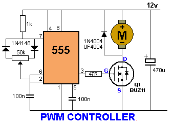
PWM Controller 555 timer circuits
Saturday, 7 January 2017
Using the high low side driver IR2110 explanation and plenty of example circuits
In many situations, we need to use MOSFETs configured as high-side switches. Many a times we need to use MOSFETs configured as high-side and low-side switches. Such as in bridge circuits. In half-bridge circuits, we have 1 high-side MOSFET and 1 low-side MOSFET. In full-bridge circuits we have 2 high-side MOSFETs and 2 low-side MOSFETs. In such situations, there is a need to use high-side drive circuitry alongside low-side drive circuitry. The most common way of driving MOSFETs in such cases is to use high-low side MOSFET drivers. Undoubtedly, the most popular such driver chip is the IR2110. And in this article/tutorial, I will talk about the IR2110.
You can download the IR2110 datasheet from the IR website. Here's the download link:
www.irf.com/product-info/datasheets/data/ir2110.pdf
First let’s take a look at the block diagram and the pin assignments and pin definitions (also called lead assignments and lead definitions):

Fig. 1 - IR2110 block diagram (click on image to enlarge)

Fig. 2 - IR2110 Pin/Lead Assignments (click on image to enlarge)

Fig. 3 - IR2110 Pin/Lead Definitions (click on image to enlarge)
Notice that the IR2110 comes in two packages – 14 pin through-hole PDIP package and the 16-pin surface mount SOIC package.
Now let's talk about the different pins.
Now let's talk about the different pins.
VCC is the low-side supply and should be between 10V and 20V. VDD is the logic supply to the IR2110. It can be between +3V to +20V (with reference to VSS). The actual voltage you choose to use depends on the voltage level of your input signals. Here’s the chart:

Fig. 4 - IR2110 Logic "1" Input Threshold vs VDD (click on image to enlarge)
It is common practice to use VDD = +5V. When VDD = +5V, the logic 1 input threshold is slightly higher than 3V. Thus when VDD = +5V, the IR2110 can be used to drive loads when input “1” is higher than 3 point something volts. This means that it can be used for almost all circuits, since most circuits tend to have around 5V outputs. When you’re using microcontrollers the output voltage will be higher than 4V (when the microcontroller has VDD = +5V, which is quite common). When you’re using SG3525 or TL494 or other PWM controller, you are probably going to have them powered off greater than 10V, meaning the outputs will be higher than 8V when high. So, the IR2110 can be easily used.
You may lower the VDD down to about 4V if you’re using a microcontroller or any chip that gives output of 3.3V (eg dsPIC33). While designing circuits with the IR2110, I had noticed that sometimes the circuit didn’t work properly when IR2110 VDD was selected as less than +4V. So, I do not recommend using VDD less than +4V.
In most of my circuits, I do not have signal levels which have voltages less than 4V as high and so I use VDD = +5V.
If for some reason, you have signals levels with logic “1” having lower than 3V, you will need a level converter / translator that will boost the voltage to acceptable limits. In such situations, I recommend boosting up to 4V or 5V and using IR2110 VDD = +5V.
Now let’s talk about VSS and COM. VSS is the logic supply ground. COM is “low side return” – basically, low side drive ground connection. It seems that they are independent and you might think you could perhaps isolate the drive outputs and drive signals. However, you’d be wrong. While they are not internally connected, IR2110 is a non-isolated driver, meaning that VSS and COM should both be connected to ground.
HIN and LIN are the logic inputs. A high signal to HIN means that you want to drive the high-side MOSFET, meaning a high output is provided on HO. A low signal to HIN means that you want to turn off the high-side MOSFET, meaning a low output is provided on HO. The output to HO – high or low – is not with respect to ground, but with respect to VS. We will soon see how a bootstrap circuitry (diode + capacitor) – utilizing VCC, VB and VS – is used to provide the floating supply to drive the MOSFET. VS is the high side floating supply return. When high, the level on HO is equal to the level on VB, with respect to VS. When low, the level on HO is equal to VS, with respect to VS, effectively zero.
A high signal to LIN means that you want to drive the low-side MOSFET, meaning a high output is provided on LO. A low signal to LIN means that you want to turn off the low-side MOSFET, meaning a low output is provided on LO. The output on LO is with respect to ground. When high, the level on LO is equal to the level of VCC, with respect to VSS, effectively ground. When low, the level on LO is equal to the level on VSS, with respect to VSS, effectively zero.
SD is used as shutdown control. When this pin is low, IR2110 is enabled – shutdown function is disabled. When this pin is high, the outputs are turned off, disabling the IR2110 drive.
Now let’s take a look at the common IR2110 configuration for driving MOSFETs in both high and low side configurations – a half bridge stage.

Fig. 5 - Basic IR2110 circuit for driving half-bridge (click on image to enlarge)
D1, C1 and C2 along with the IR2110 form the bootstrap circuitry. When LIN = 1 and Q2 is on, C1 and C2 get charged to the level on VB, which is one diode drop below +VCC. When LIN = 0 and HIN = 1, this charge on the C1 and C2 is used to add the extra voltage – VB in this case – above the source level of Q1 to drive the Q1 in high-side configuration. A large enough capacitance must be chosen for C1 so that it can supply the charge required to keep Q1 on for all the time. C1 must also not be too large that charging is too slow and the voltage level does not rise sufficiently to keep the MOSFET on. The higher the on time, the higher the required capacitance. Thus, the lower the frequency, the higher the required capacitance for C1. The higher the duty cycle, the higher the required capacitance for C1. Yes, there are formulae available for calculating the capacitance. However, there are many parameters involved, some of which we may not know – for example, the capacitor leakage current. So, I just estimate the required capacitance. For low frequencies such as 50Hz, I use between 47µF and 68µF capacitance. For high frequencies like 30kHz to 50kHz, I use between 4.7µF and 22µF. Since we’re using an electrolytic capacitor, a ceramic capacitor should be used in parallel with this capacitor. The ceramic capacitor is not required if the bootstrap capacitor is tantalum.
D2 and D3 discharge the gate capacitances of the MOSFET quickly, bypassing the gate resistors, reducing the turn off time. R1 and R2 are the gate current-limiting resistors.
+MOSV can be up to a maximum of 500V.
+VCC should be from a clean supply. You should use filter capacitors and decoupling capacitors from +VCC to ground for filtering.
Now let’s look at a few example application circuits of the IR2110.

Fig. 6 - IR2110 circuit for high-voltage half-bridge drive (click on image to enlarge)

Fig. 7 - IR2110 circuit for high-voltage full-bridge drive with independent switch control (click on image to enlarge)
In Fig. 7 we see the IR2110 being used to drive a full bridge. The functionality is simple and you should understand it by now. A common thing that is often done is that, HIN1 is tied/shorted to LIN2 and HIN2 is tied/shorted to LIN1, enabling the control of all 4 MOSFETs from 2 signal inputs, instead of 4 as shown below in Fig. 8.

Fig. 8 - IR2110 circuit for high-voltage full-bridge drive with tied switch control - control with 2 input signals (click on image to enlarge)

Fig. 9 - Using the IR2110 as a single high-voltage high-side driver (click on image to enlarge)
In Fig. 9 we see the IR2110 being used as a single high-side driver. The circuit is simple enough and follows the same functionality described above. One thing to remember is that, since there is no low-side switch, there must a load connected from OUT to ground. Otherwise the bootstrap capacitors can not charge.

Fig. 10 - Using the IR2110 as a single low-side driver (click on image to enlarge)

Fig. 11 - Using the IR2110 as a dual low-side driver (click on image to enlarge)
--------------------------------------------------------------------------------------------------------------------------------------------------------------------------------------------------------------
http://www.irf.com/technical-info/appnotes/an-978.pdf
--------------------------------------------------------------------------------------------------------------------------------------------------------------------------------------------------------------
If you've had failures with IR2110 and had driver after driver, MOSFET after MOSFET get damaged, burn and fail, I'm pretty sure that it's due to you not using gate-to-source resistors, assuming of course that you designed the IR2110 driver stage properly. NEVER OMIT THE GATE-TO-SOURCE RESISTORS. If you're curious, you can read about my experience with them here (I have also explained the reason that the resistors prevent damage):
http://www.blogspot.com/2016/10/magic-of-knowledge.html
For further reading, you should go through this:
http://www.irf.com/technical-info/appnotes/an-978.pdf
I have seen in many forums that people struggle with designing circuits with IR2110. I too had a lot of difficulty before I could confidently and consistently build successful driver circuits with IR2110. I have tried to explain the application and use of IR2110 thoroughly through explanation and plenty of examples and hope that it helps you in your endeavors with IR2110.
Thursday, 5 January 2017
6 12 Volt audio amplifier circuits

The above is an amplifier circuit using supply voltages from 6 volts DC to 12 Volt DC. Power output of the amplifier is quite low with only 1 Watt 8 ohm impedance. You can apply this to the audio signal amplifiers that require strengthening are not so large as in the pocket radio.Part List :
R1 = 100K
R2 = 39R
R3 = 100R
C1 = 100nF
C2 = 100uF
C3 = 100uF
C4 = 100uF
C5 = 470uF
C6 = 100nF
C7 = 68pF
C8 = 1nF
C9 = 47uF
IC = SFC2790C
Saturday, 10 December 2016
Dual Power Supply Circuits
This is a bench top power supply that can be used to power circuits or devices during development work in the lab. More specifically it is an adjustable, tracking, dual rail supply which means there are two supply voltages, one positive, one negative, that are adjusted by a common potentiometer such that supply voltages are equal in magnitude. It is capable of supplying up to +/- 15V DC at up to 1A. This is sufficient for the majority of small signal electronic projects.
Dual Power Suplly Circuit diagram.
 |
| Click to view larger |
Power Supply circuit above shows the circuit layout for this project. A centre tapped transformer (TR1) is used with two 12V secondary windings with its centre tap tied to ground. This allows positive and negative voltages to be generated with respect to the central ground. Rectification follows based upon the bridge rectifier (BR1) and smoothing capacitors (C1, C2, C4 and C5).
Two linear regulators are used, an LM317 on the positive side and an LM337 on the negative side. These regulators keep the supply voltage constant for a varying load up to a load current of around 1A. The voltage adjustment is achieved through potentiometers RV1 and RV2 in the positive side of the circuit. The clever part of this circuit comes from the mirroring of the positive voltage adjustment to the negative side via the op-amp U2 to give the circuit its tracking nature.
The op-amp U2 has its positive input tied to ground via a 4K7 resistor. This means that, providing there is negative feedback around the op-amp, the op-amp will endeavour to make its negative input also at ground or 0V. The negative feedback is arranged by the output of the op-amp U2 driving the Adjust pin of the negative regulator U3 and by resistors R3 and R4. The op-amp U2 sets the voltage on the adjust pin of U3 such that the voltage at its negative input is 0V. Also as R3 and R4 are equal, the positive and negative regulated voltages must then be equal in magnitude.
An analogue meter is driven from the positive side to give an indication of the voltage setting. Two switches are used to allow the positive and negative supplies to be turned on/off independently and there are also two LED acting as indicators.
Dual Power Supply Construction
This power supply circuit was built up on Veroboard as it is quite simple to build. Heatsinks can be mounted to the two regulators to improve the current drive capability. The transformer and circuit were mounted inside a wooden box. If a metal box is used the box must be connected to mains earth to prevent a shock hazard. Figure 2 shows a picture of the finished unit. It should be noted that this box is rather shabby and the author has been meaning to improve it for a while but it does do the job nicely.
Friday, 9 December 2016
PWM Controller 555 timer circuits
Monday, 7 November 2016
Oscillator 50 300 MHz Colpitts Type Circuits Diagram
This is the simple project of Oscillator 50-300 MHz Colpitts Type Circuits Diagram. Simple but high efficiency of this circuit is a Colpitts oscillator for VHF. Ideal for higher frequencies above 50 MHz, Colpitts oscillators are used for VHF parasitic capacitance of the circuit is in parallel with the feedback capacitance desired and causes no undesired spurious resonances which may occur with the Hartley oscillator.
The circuit above is a VCO FM, it is a grassroots project with grounded feedback from collector to emitter. A Colpitts oscillator is a series of designs for electronic oscillator circuits using a combination of an inductance with a capacitor to determine the frequency.

Make an Oscillator 50-300 MHz Colpitts Type Circuits Diagram
Subscribe to:
Posts (Atom)