Showing posts with label remote. Show all posts
Showing posts with label remote. Show all posts
Monday, 6 March 2017
Make a Hi End RF Remote Control Circuit
Building a hi-end remote control device using very few components today looks pretty plausible. The proposed remote control light switch circuit idea provides you with the opportunity of building and owning this amazing device through simple instructions. Moreover the unit provides a 4-bit data to be exchanged between the transmitter and the receiver modules.
This Hi-tech remote control light switch enables you to control four individual lights or any electrical appliance for that matter from any corner of your house remotely using a single tiny remote control hand set. Build the “amazement” right on your workbench.
Imagine switching a light, a fan, washing machine, computer or similar gadgets from any corner of your room without taking a step! Doesn't that sound great? Controlling a particular gadget remotely through a single flick of your finger definitely feels very amusing and amazing too. It also gives you the comfort of doing an act without moving or getting up from a particular position.
The present circuit idea of a remote control light switch enables you controlling not only just a single light but four different electrical gadgets individually using a single remote control hand set.
Let’s try to understand its circuit functioning in details.
Circuit Description:

I have already discussed the wireless control modules through one of my previous articles, let’s summarize the entire description yet again and also learn how simply the stages may be configured into the proposed unit.
The first figure shows a standard transmitter module using the RF generator chip TWS-434 and the associated encoder chip the HOLTEK’s HT-12E.
The IC TWS-434 basically does the function of manufacturing and transmitting the carrier waves into the atmosphere.
However every carrier signal needs modulation for its proper execution, i.e. it needs to be embedded with a data that becomes the information for the receiving end.
This function is done through its complementing part – the HT-12E 4-bit encoder chip. It has got four inputs, which can be triggered discretely by giving them a ground pulse individually. Each of these inputs produces coding which are distinctly different to each other and become their unique signature definitions.
The encoded pulse from the relevant input is transferred to the IC TWS-434 which carries forward the data and modulates it with the generated carrier waves and finally transmits it into the atmosphere.
The above operations take care of the transmitter unit.

The receiver module does the above operations just in the opposite manner.
Here, the IC RWS-434 forms the receiving part of the module; its antenna anticipates the available encoded pulses from the atmosphere and captures them immediately as they are sensed.
The captured signals are relayed forward to the next stage – the signal decoder stage.
Just like the transmitter module, here too a complementing device the HOLTEK’s HT-12D is employed to revert the received encoded signals.
This decoding chip also consists of a 4-bit decoding circuitry and their outputs.
The received data is appropriately analyzed and decoded.
The decoded information gets terminated out through the relevant pin-out of the IC.
This output is in the form of a logic high pulse whose duration depends on the duration of the ground pulse applied to the encoder chip of the transmitter module.
The above output is fed to a Flip-Flop circuit using the IC 4017, whose output is finally used to switch the output load via a relay driver circuitry.
One such flip/flop idea is shown you may construct four of them to access each of the generated 4-bit data discretely and control four gadgets individually.

Whether you use it as a remote control light switch or to control many more appliances……the option is all yours.

Wednesday, 15 February 2017
Simple Remote Control Mains Switch
As the only electronics engineer in my =family and circle of friends, it is some-times not possible to evade an appeal for help. This time the request came from a friendly elderly lady in a retirement home. In her room the light switch by the door and the pull cord above the bed operate the light fitting on the ceiling in the middle of the room. However, she would prefer that her standing lamp was operated by these switches instead, since she does not actually have a light fitting mounted on the ceiling. This standing lamp has an on/of f switch in the power cord and is plugged into a power point. However, it stands rather far from the bed so that she always has to find her way in the dark. A wireless operated power point is not really a consideration, because it is just a matter of time before the remote is lost. Or maybe not?
Remote Control Mains Switch Circuit Diagram :

Behold a feasible circuit. Buy a wireless power point and an enclosure that is big enough for the remote control and a small piece of prototyping board. On the proto-typing board build the circuit according to the accompanying schematic and (care-fully) open the remote control and solder wires to the push buttons for ‘on’ and ‘off’. Measure if these are polarised and if that is the case connect them to the 4N25 opto-couplers as shown in the schematic, where pin 5 has a higher voltage than pin 4.
The operation is as follows. The lady operates the pull cord or light switch to turn the light on. This causes the mains voltage to be applied to the transformer. The relay is activated which charges C1. While C1 charges, a small current flows through optocoupler 1. The result is that the ‘on’ button on the remote control is pressed. The remote control switches the corresponding power point on and to which the standing lamp is connected. The standing lamp will therefore now turn on. Capacitor C2 is charged at the same time. If the lady pulls the cord again, or if she operates the switch near the door, the relay will de-energise and C2 discharges across optocoupler #2. This operates the ‘off’ contact of the remote control and the light goes out.
The remote control continuous to operate from its normal battery and the white enclosure is attached to the ceiling in place of the light fitting. Diode D1 ensures that C1 is discharged when the relay de-energises. D2 ensures that C2 cannot discharge across the relay, but only across optocoupler 2.
Author : Jaap van der Graaff - Copyright :Elektor
Wednesday, 8 February 2017
Simple TV Remote Control Jammer Circuit Diagram
This is the Simple TV Remote Control Jammer Circuit Diagram. Do you have an incessant channel hopper that is driving you crazy? Or perhaps you simply want to enforce your own selections. The TV Remote Control Jammer will do the trick.
Simple TV Remote Control Jammer Circuit Diagram

This circuit is a redo of an older design which is not effective on modern remotes. Modern remote controls are hard to jam but with a little care this circuit will do the job. The circuit is just a flasher operating at 40 kHz which is the carrier frequency used by common remote controls. The strong 40 kHz infrared flashing interferes with the signal from the remote.
The 50k potentiometer is adjusted to achieve a 40 kHz flash rate (around 20 kohms) and this adjustment is fairly critical. When it is set properly and the LEDs are pointed directly at the receiver's photodiode, the remote control will stop working. The LEDs are operating at about 30 mA when on but the duty cycle is low and the circuit only draws about 7 mA.
Trouble may be encountered if the frequency is set wrong, the LEDs are not pointed correctly, or if the remote is a real brute. More light may be had by adding another resistor and diode string from the collector to the switch but the most likely problem is the frequency adjustment. Use a 10-turn pot and adjust it slowly while changing channels. Or use a frequency counter or oscilloscope to set the frequency, if possible. Make sure that the current drain is about 7 mA - if not, check the polarity of the diodes. A photodiode infrared receiver is handy for checking the light output and comparing it to the remote's.
Simple TV Remote Control Jammer Circuit Diagram
This circuit is a redo of an older design which is not effective on modern remotes. Modern remote controls are hard to jam but with a little care this circuit will do the job. The circuit is just a flasher operating at 40 kHz which is the carrier frequency used by common remote controls. The strong 40 kHz infrared flashing interferes with the signal from the remote.
The 50k potentiometer is adjusted to achieve a 40 kHz flash rate (around 20 kohms) and this adjustment is fairly critical. When it is set properly and the LEDs are pointed directly at the receiver's photodiode, the remote control will stop working. The LEDs are operating at about 30 mA when on but the duty cycle is low and the circuit only draws about 7 mA.
Trouble may be encountered if the frequency is set wrong, the LEDs are not pointed correctly, or if the remote is a real brute. More light may be had by adding another resistor and diode string from the collector to the switch but the most likely problem is the frequency adjustment. Use a 10-turn pot and adjust it slowly while changing channels. Or use a frequency counter or oscilloscope to set the frequency, if possible. Make sure that the current drain is about 7 mA - if not, check the polarity of the diodes. A photodiode infrared receiver is handy for checking the light output and comparing it to the remote's.
Saturday, 31 December 2016
UHF FM Remote Control Receiver Circuit
The receiver is intended primarily for use with the remote control UHF transmitter described in the preceding article.
It is a super-regenerative type with an active RF amplifier, T1. The antenna signal is applied to the input inductor via a BNC socket, K1. The input circuit is tuned by trimmer C4. The amplified RF signal is applied to the input of the super-regenerative stage based on transistor T2. Although the oscillator is, strictly speaking, not tuned, it will lock on to the amplified RF signal applied via coupling capacitor C7. The low-frequency modulation component is extracted from the oscillator signal with the aid of low-pass filter, R6-R7-C12-R8-C13. The signal level at the demodulator output is 50 to 800 mVpp, so that further amplification is required·before the signal can be applied to a digital input. The inductors in the RF amplifier input and output are made from 1 mm dia. silver-plated wire. The length of the pieces of wire is indicated by the component overlay. The wires run at a height of about 3 mm above the board surface. Note that the stator terminal of C4 is bent upwards and soldered direct to the input inductor. The same goes for junction C6-C7, which is soldered ‘in the air‘, directly op to the hot end of the inductor wire. Inductor L1 consists of 12 turns of 0.6-mm dia. enamelled copper wire. Its internal diameter is 3 mm. Each of chokes g and L3 consists of 4 turns of 0.2-mm dia enamelled copper wire through a 3 mm long ferrite bead. Capacitor C8 is a surface-mount technology (SMT) type which is fitted at the solder side of the board, as are the BFG65 and the BFQSO. The type indica- tion printed on the transistors is legible from the component side of the board. As indicated by the dashed lines on the component overlay, the super-regenerative section of the circuit must be screened from the rest. To do this, it is best to solder a 20 mm high tin plate box on to the PCB as indicated.
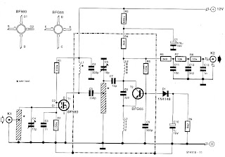
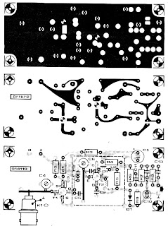
It is a super-regenerative type with an active RF amplifier, T1. The antenna signal is applied to the input inductor via a BNC socket, K1. The input circuit is tuned by trimmer C4. The amplified RF signal is applied to the input of the super-regenerative stage based on transistor T2. Although the oscillator is, strictly speaking, not tuned, it will lock on to the amplified RF signal applied via coupling capacitor C7. The low-frequency modulation component is extracted from the oscillator signal with the aid of low-pass filter, R6-R7-C12-R8-C13. The signal level at the demodulator output is 50 to 800 mVpp, so that further amplification is required·before the signal can be applied to a digital input. The inductors in the RF amplifier input and output are made from 1 mm dia. silver-plated wire. The length of the pieces of wire is indicated by the component overlay. The wires run at a height of about 3 mm above the board surface. Note that the stator terminal of C4 is bent upwards and soldered direct to the input inductor. The same goes for junction C6-C7, which is soldered ‘in the air‘, directly op to the hot end of the inductor wire. Inductor L1 consists of 12 turns of 0.6-mm dia. enamelled copper wire. Its internal diameter is 3 mm. Each of chokes g and L3 consists of 4 turns of 0.2-mm dia enamelled copper wire through a 3 mm long ferrite bead. Capacitor C8 is a surface-mount technology (SMT) type which is fitted at the solder side of the board, as are the BFG65 and the BFQSO. The type indica- tion printed on the transistors is legible from the component side of the board. As indicated by the dashed lines on the component overlay, the super-regenerative section of the circuit must be screened from the rest. To do this, it is best to solder a 20 mm high tin plate box on to the PCB as indicated.
For the transmitter circuit : UHF FM Remote Control Transmitter Circuit
Tuesday, 22 November 2016
LBL Activated Remote Control Circuit Diagram
This is the simple Laser Beam Light Activated Remote Control Circuit Diagram. The following post illustrates a simple light toggled/operated remote control circuit, which can be activated by an ordinary flashlight or more effectively through a laser beam unit (key chain type).
LBL Activated Remote Control Circuit Diagram

The circuit idea may be understood with the below mentioned points:
Parts List
LBL Activated Remote Control Circuit Diagram
The circuit idea may be understood with the below mentioned points:
- Transistor T1 alnog with R3, C6 and the LDR itself forms a simple light sensor stage.
- The LDR is connected across the base of the transistor and the positive supply such that when light falls over the LDR, T1 receives the required base bias and conducts.
- When T1 conducts, the high potential at pin 14 of IC1 is pulled to logic low. However since a logic low wouldn't effect pin#14, IC1 does not respond as yet.
- The moment light on the LDR is switched OFF, T1 is switched OFF and pin#14 now instantly receives a subsequent logic high via R5.....now IC1 responds, and shifts it's output from pin#3 to pin#2. This makes pin#3 logic low, activating T2, and the preceding relay driver stage.
- The above condition persists until the LDR is illuminated again with a flashlight or with a laser beam.
- The above operation alternately toggles the output ON and OFF providing the required toggling actions to the connected load.
- The LDR must be covered inside an opaque pipe, about an inch long so that the ambient light stays obstructed from the LDR.
- The angle of the pipe should be kept in a such a way that it facilitates easy focusing of the light beam toward the LDR.
- C6 ensures that the system does not respond to accidental spurious light beams in case it finds its way inside the pipe, and over the LDR.
Parts List
- R3,R4,R5,R6,R7 = 2K2
- T1 = BC547,
- T2 = BC557
- IC1 = 4017
- IC2 = 7812
- ALL DIODES = 1N4007
- C6,C7 = 10uF/25V
- C8 = 1000uF/25V
- C10 = 0.1uF
Wednesday, 16 November 2016
IR Remote Control Extender Mark 2
This is an improved IR remote control extender circuit. It has high noise immunity, is resistant to ambient and reflected light and has an increased range from remote control to the extender circuit of about 7 meters. It should work with any domestic apparatus that use 36-38kHz for the IR carrier frequency. Please note that this is NOT compatible with some satellite receivers that use 115KHz as a carrier frequency.

Notes:
The main difference between this version and the previous circuit, is that this design uses a commercially available Infra Red module. This module, part number IR1 is available from Harrison Electronics in the UK. The IR module contains a built in photo diode, amplifier circuit and buffer and decoder. It is centerd on the common 38kHz carrier frequency that most IR controls use. The module removes most of the carrier allowing decoded pulses to pass to the appliance. Domestic TV's and VCR's use extra filtering is used to completely remove the carrier. The IR1 is packaged in a small aluminium case, the connections viewed from underneath are shown below:
Infra Red Module, IR1 Pinout
How It works:
The IR1 module (IC3) operates on 5 Volt dc. This is provided by the 7805 voltage regulator, IC1. Under quiescent (no IR signal) conditions the voltage on the output pin is high, around 5 volts dc. This needs to be inverted and buffered to drive the IR photo emitter LED, LED2. The buffering is provided by one gate (pins 2 & 3) of a hex invertor the CMOS 4049, IC2. The IR1 module can directly drive TTL logic,but a pull-up resistor, R4 is required to interface to CMOS IC's. This resistor ensures that the signal from a remote control will alternate between 0 and 5 volts. As TTL logic levels are slightly different from CMOS, the 3.3k resistor R4 is wired to the +5 volt supply line ensuring that the logic high signal will be 5 volts and not the TTL levels 3.3 volts. The resistor does not affect performance of the IR module, but DOES ensure that the module will correctly drive the CMOS buffer without instability.
The output from the 4049 pin 2 directly drives transistor Q1, the 10k resistor R1 limiting base current. LED1 is a RED LED, it will flicker to indicate when a signal from a remote control is received. Note that in this circuit, the carrier is still present, but at a reduced level, as well as the decoded IR signal. The CMOS 4049 and BC109C transistor will amplify both carrier and signal driving LED2 at a peak current of about 120 mA when a signal is received. If you try to measure this with a digital meter, it will read much less, probably around 30mA as the meter will measure the average DC value, not the peak current. Any equipment designed to work between 36 and 40kHz should work, any controls with carrier frequencies outside this limit will have reduced range, but should work. The exception here is that some satellite receivers have IR controls that use a higher modulated carrier of around 115KHz. At present, these DO NOT work with my circuit, however I am working on a Mark 3 version to re-introduce the carrier.
Parts List:
C1 100u 10V
C2 100n polyester
R1 10k
R2 1k
R3 33R 1W
R4 3k3
Q1 BC109C
IC1 LM7805
IC2 CMOS 4049B
IC3 IR1 module from Harrison Electronics See Last paragraph
LED1 Red LED (or any visible colour)
LED2 TIL38 or part YH70M from Maplin Electronics
Testing:
This circuit should not present too many problems. If it does not work, arm yourself with a multimeter and perform these checks. Check the power supply for 12 Volt dc. Check the regulator output for 5 volt dc. Check the input of the IR module and also Pin 1 of the 4049 IC for 5 volts dc. With no remote control the output at pin 2 should be zero volts. Using a remote control pin 2 will read 5 volts and the Red LED will flicker. Measuring current in series with the 12 volt supply should read about 11mA quiescent, and about 40/50mA with an IR signal. If you still have problems measure the voltage between base and emitter of Q1. With no signal this should be zero volts, and rise to 0.6-0.7 volts dc with an IR signal. Any other problems, please email me, but please do the above tests first.
PCB Template:
Once again a PCB template has been kindly drafted for this project by Domenico.

A magnified view showing the component side is shown below:

Alternatives to IC3:
The part number IR1 from Harrison Electronics is no longer available. They do supply an alternative IR decoder which I have tested and works. Other alternative Infrared decoders are shown below, note however that all DO NOT share the same pinout. I advise anyone making this to check the corresponding data sheets.
Vishay TSOP 1738
Vishay TSOP 1838
Radio Shack 276-0137
Sony SBX 1620-12
Sharp GP1U271R
Equipment Controlled Successfully:
If you have built this circuit and it works successfullt please let me know and I will build the list. Email details of the Manufacturer, device and remote control model number. The remote model number is usually on the front or back of the remote.
Technics CDP770 Remote: EUR64713
Notes:
The main difference between this version and the previous circuit, is that this design uses a commercially available Infra Red module. This module, part number IR1 is available from Harrison Electronics in the UK. The IR module contains a built in photo diode, amplifier circuit and buffer and decoder. It is centerd on the common 38kHz carrier frequency that most IR controls use. The module removes most of the carrier allowing decoded pulses to pass to the appliance. Domestic TV's and VCR's use extra filtering is used to completely remove the carrier. The IR1 is packaged in a small aluminium case, the connections viewed from underneath are shown below:
Infra Red Module, IR1 Pinout
How It works:
The IR1 module (IC3) operates on 5 Volt dc. This is provided by the 7805 voltage regulator, IC1. Under quiescent (no IR signal) conditions the voltage on the output pin is high, around 5 volts dc. This needs to be inverted and buffered to drive the IR photo emitter LED, LED2. The buffering is provided by one gate (pins 2 & 3) of a hex invertor the CMOS 4049, IC2. The IR1 module can directly drive TTL logic,but a pull-up resistor, R4 is required to interface to CMOS IC's. This resistor ensures that the signal from a remote control will alternate between 0 and 5 volts. As TTL logic levels are slightly different from CMOS, the 3.3k resistor R4 is wired to the +5 volt supply line ensuring that the logic high signal will be 5 volts and not the TTL levels 3.3 volts. The resistor does not affect performance of the IR module, but DOES ensure that the module will correctly drive the CMOS buffer without instability.
The output from the 4049 pin 2 directly drives transistor Q1, the 10k resistor R1 limiting base current. LED1 is a RED LED, it will flicker to indicate when a signal from a remote control is received. Note that in this circuit, the carrier is still present, but at a reduced level, as well as the decoded IR signal. The CMOS 4049 and BC109C transistor will amplify both carrier and signal driving LED2 at a peak current of about 120 mA when a signal is received. If you try to measure this with a digital meter, it will read much less, probably around 30mA as the meter will measure the average DC value, not the peak current. Any equipment designed to work between 36 and 40kHz should work, any controls with carrier frequencies outside this limit will have reduced range, but should work. The exception here is that some satellite receivers have IR controls that use a higher modulated carrier of around 115KHz. At present, these DO NOT work with my circuit, however I am working on a Mark 3 version to re-introduce the carrier.
Parts List:
C1 100u 10V
C2 100n polyester
R1 10k
R2 1k
R3 33R 1W
R4 3k3
Q1 BC109C
IC1 LM7805
IC2 CMOS 4049B
IC3 IR1 module from Harrison Electronics See Last paragraph
LED1 Red LED (or any visible colour)
LED2 TIL38 or part YH70M from Maplin Electronics
Testing:
This circuit should not present too many problems. If it does not work, arm yourself with a multimeter and perform these checks. Check the power supply for 12 Volt dc. Check the regulator output for 5 volt dc. Check the input of the IR module and also Pin 1 of the 4049 IC for 5 volts dc. With no remote control the output at pin 2 should be zero volts. Using a remote control pin 2 will read 5 volts and the Red LED will flicker. Measuring current in series with the 12 volt supply should read about 11mA quiescent, and about 40/50mA with an IR signal. If you still have problems measure the voltage between base and emitter of Q1. With no signal this should be zero volts, and rise to 0.6-0.7 volts dc with an IR signal. Any other problems, please email me, but please do the above tests first.
PCB Template:
Once again a PCB template has been kindly drafted for this project by Domenico.
The part number IR1 from Harrison Electronics is no longer available. They do supply an alternative IR decoder which I have tested and works. Other alternative Infrared decoders are shown below, note however that all DO NOT share the same pinout. I advise anyone making this to check the corresponding data sheets.
Vishay TSOP 1738
Vishay TSOP 1838
Radio Shack 276-0137
Sony SBX 1620-12
Sharp GP1U271R
Equipment Controlled Successfully:
If you have built this circuit and it works successfullt please let me know and I will build the list. Email details of the Manufacturer, device and remote control model number. The remote model number is usually on the front or back of the remote.
Technics CDP770 Remote: EUR64713
Tuesday, 8 November 2016
Infrared Remote Tester
Description
 Parts:
Notes:
Source http://www.extremecircuits.net/2009/07/infrared-remote-tester.html
A very simple device allowing a quick check of common Infra-red Remote-Controls can be useful to the electronics amateur, frequently asked to repair or test these ubiquitous devices. A reliable circuit was designed with a handful of components: the LED will flash when any of the Remote-Control push buttons will be pressed. The side of the Remote-Control bearing the IR emitting diode(s) must be directed towards the Photo Transistor (Q1) of the checker circuit: maximum distance should not exceed about 20 - 25cm.
Circuit Diagram: - R1 = 470K
- R2 = 47R
- D1 = LED Any Type
- Q1 = Photo Transistor
- Q2 = BC327
- B1 = 3V Battery or 2 AA cell
- Current drawing of the circuit is less than 1mA when the LED illuminates and 0mA when no signal is picked-up by the Photo Transistor: therefore, SW1 can be omitted.
- SW1 will be SPST Toggle or Slider Switch
Source http://www.extremecircuits.net/2009/07/infrared-remote-tester.html
Thursday, 3 November 2016
UHF FM Remote Control Transmitter Circuit
This low-power UHF FM transmitter is intended for remote control applications such as garage doors and wireless alarm systems.
It is a single transistor design that operates at a frequency reserved for low-power wireless signalling. The operating frequency is determined by a resonator, F11. The following types may be used: UK: Type R2528 for 418 MHz; USA: Type Rl53O for 315 MHz; Holland, Belgium, Germany: Type R2554 for 433;92 MHZ: France: Type R2523 for 224.5 MHZ. The transmitter is frequency-modulated by an audio (or digital) signal applied to the junction of a varactors D1, D2 via R3. The varactors effectively change the shunt capacitance of the resonator as a function of the modulation signal, which results in FM. The design may be changed to produce AM (amplitude-modulation) by omitting components D1, D2, R2, R3 and R6, and interconnecting points ‘A’ and ‘B‘. Transistor T1 is fitted at the solder side of the printed circuit board, as indicated by the dashed outline on the component overlay. Also on this side of the PCB is a short wire link (use silver plated wire) that connects strip line inductor L1 to the positive supply track that runs in parallel with it. The position of the wire link d·epends on the transmit frequency. The lower the frequency, the more inductance is required, that is, the further the link has to be ‘moved' towards the edge of the PCB. Some experimenting may be necessary to find the best position. Start by setting the trimmer, C3, about mid-way, and fit the wire link about ‘half way’ on the strip line. Monitor the received signal, and adjust C3 until a maximum is found. If you can not find,a maximum, try moving the wire link either towards the transistor (smaller inductance), or towards the PCB edge (greater inductance). The best position is that at which C3 ‘peaks‘ when set about mid-way. Since we are dealing with a UHF circuit, it goes without saying that all component terminals must be kept as short as possible. The transmitter must be housed in a plastic enclosure to enable it to radiate.


It is a single transistor design that operates at a frequency reserved for low-power wireless signalling. The operating frequency is determined by a resonator, F11. The following types may be used: UK: Type R2528 for 418 MHz; USA: Type Rl53O for 315 MHz; Holland, Belgium, Germany: Type R2554 for 433;92 MHZ: France: Type R2523 for 224.5 MHZ. The transmitter is frequency-modulated by an audio (or digital) signal applied to the junction of a varactors D1, D2 via R3. The varactors effectively change the shunt capacitance of the resonator as a function of the modulation signal, which results in FM. The design may be changed to produce AM (amplitude-modulation) by omitting components D1, D2, R2, R3 and R6, and interconnecting points ‘A’ and ‘B‘. Transistor T1 is fitted at the solder side of the printed circuit board, as indicated by the dashed outline on the component overlay. Also on this side of the PCB is a short wire link (use silver plated wire) that connects strip line inductor L1 to the positive supply track that runs in parallel with it. The position of the wire link d·epends on the transmit frequency. The lower the frequency, the more inductance is required, that is, the further the link has to be ‘moved' towards the edge of the PCB. Some experimenting may be necessary to find the best position. Start by setting the trimmer, C3, about mid-way, and fit the wire link about ‘half way’ on the strip line. Monitor the received signal, and adjust C3 until a maximum is found. If you can not find,a maximum, try moving the wire link either towards the transistor (smaller inductance), or towards the PCB edge (greater inductance). The best position is that at which C3 ‘peaks‘ when set about mid-way. Since we are dealing with a UHF circuit, it goes without saying that all component terminals must be kept as short as possible. The transmitter must be housed in a plastic enclosure to enable it to radiate.
The NEXT post discusses the Receiver Circuit: UHF FM Remote Control Receiver Circuit
Wednesday, 28 September 2016
Get Wiring diagram hampton bay ceiling fan remote
Wiring diagram hampton bay ceiling fan remote


Wiring diagram hampton bay ceiling fan remote
Hampton bay ceiling fan wiring | ehow, Hampton bay ceiling fan wiring. the way you wire the hampton bay ceiling fan will depend on the type of fan you purchase. a standard ceiling fan is wired differently.
Hampton bay ventilation fan wiring - doityourself.com, I tried finding at hampton bay (home depot) but not much luck. i'm guessing it didn't come with an instruction sheet. it appears that the wiring diagram is on the.
Harbor breeze ceiling fan light kit wiring diagram, Harbor breeze ceiling fan light kit wiring diagram. double ceiling fan. wiring bathroom exhaust fans with light. 3 speed ceiling fan switch wiring diagram. hunter.
Hampton bay trentino ii 60 in. indoor/outdoor white, The trentino ii 60 in. indoor/outdoor white ceiling fan has a transitional design but packs a heavy punch for any room or area. if air flow is what you are looking.
How to install a ceiling fan with remote control, Author: terry peterman this post and detailed video describe how to install a ceiling fan with remote control. the addition of a remote control to a.
Hunter ceiling fans with lights & modern flush mount, Hunter ceiling fans make some of the best ceiling fans with lights in classic, timeless styles to contemporary and modern ceiling fans [learn more below]..
Sunday, 25 September 2016
Topic Wiring diagram for ceiling fan remote control
Wiring diagram for ceiling fan remote control


Wiring diagram for ceiling fan remote control
Ceiling fan wiring diagram #1 - ask-the-electrician, Full color ceiling fan wiring diagram shows the wiring connections to the fan and the wall switches..
Ceiling fan wiring diagram #2 - ask-the-electrician, Full color ceiling fan wiring diagram shows the wiring connections to the fan and two switches..
Ceiling fan wiring instructions, electrical wiring for, Ceiling fan wiring instructions by wire color. wiring a ceiling fan is surprisingly simple. often times it is no more complicated than the wiring of a light fixture..
Ceiling fan and light remote note: with wall control, Available at www.honeywellstore.com ceiling fan and light remote with wall control model 40015 / item # 0374122 user guide important safety instructions.
Electric standing fan motor wiring diagram - lulusoso.com, Looking for electric standing fan motor wiring diagram ? here you can find the latest products in different kinds of electric standing fan motor wiring diagram. we.
Hampton bay ceiling fan wiring | ehow, Hampton bay ceiling fan wiring. the way you wire the hampton bay ceiling fan will depend on the type of fan you purchase. a standard ceiling fan is wired differently.
Sunday, 4 September 2016
Discuss Wiring diagram yamaha 703 remote control
Wiring diagram yamaha 703 remote control


Wiring diagram yamaha 703 remote control
Internal wiring for yamaha 703 remote control - yamaha, Hi, i lost my keys, so i opened my yamaha 703 remote control. i unplugged the key switch by cutting some wires and went to my dealer in order to find a key that works..
Yamaha 703 remote control tachometer wiring - moderated, You last post or the one above this is correct except there is no gray wire in the 703 power harness from the yamaha 703 control. dave.send me an email to parts.
Yamaha 703 remote control for outboard motors - yamaha, First that all i would like to thanks everyone for the great help, i need an operation manual for the 703 control box, i bought an old boat with this box but the box.
Book library and manual by richie edmund, Book library and manual by richie edmund by html5 up. home; layouts. generic; contact; elements; submenu. option one; option two; option three; option four; sign up.
The best boat forum for answers to hard qustions about boats, This is the best boat forum on the web, it's yours! are you looking for good advice about sailboats and yacht equipment and systems? why not invest in one of my.
Edotek uk | chemical consultants | analysis | materials, Edotek is a scientific consultancy which provides technical assistance to industry and other agencies helping them to solve problems in the areas of chemistry and.
Thursday, 1 September 2016
This is Wiring diagram for a hunter ceiling fan remote
Wiring diagram for a hunter ceiling fan remote
Ceiling fan wiring diagram #1 - ask-the-electrician, Full color ceiling fan wiring diagram shows the wiring connections to the fan and the wall switches..
Hampton bay ceiling fan wiring diagram - emprendedor.link, Hampton bay ceiling fan wiring diagram. help!! light dimmer problem hunter fan w/ hampton bay remote. help wiring hampton bay ceiling fan w/ remote? â yahoo!.
Harbor breeze ceiling fan light kit wiring diagram, Harbor breeze ceiling fan light kit wiring diagram. double ceiling fan. wiring bathroom exhaust fans with light. 3 speed ceiling fan switch wiring diagram. hunter.
Hunter ceiling fans with lights & modern flush mount, Hunter ceiling fans make some of the best ceiling fans with lights in classic, timeless styles to contemporary and modern ceiling fans [learn more below]..
Universal fan and light remote control - hunter fan, Universal fan and light remote control form# 44092-01 20101215 ©2010 hunter fan co. english owner’s guide and installation manual hand-held remote and wall cradle.
I am wiring a remote control (hunter product 27185) to a fan, I am wiring a remote control (hunter product 27185) to a fan with a light kit. i am not sure what to connect the red wire (coming from the ceiling) to..
nowadays i came across the particular Wiring diagram for a hunter ceiling fan remoteDetailed information about Wiring diagram for a hunter ceiling fan remote
and your search ends here below is information relating to Wiring diagram for a hunter ceiling fan remote
here is some bit review
Pic Example Wiring diagram for a hunter ceiling fan remote


understand Wiring diagram for a hunter ceiling fan remote
what substantial girl grope girl become prosperous as for since uncover Wiring diagram for a hunter ceiling fan remote
And sure this Wiring diagram for a hunter ceiling fan remote
post useful for you even if you are a beginner though
Subscribe to:
Posts (Atom)