Showing posts with label fan. Show all posts
Showing posts with label fan. Show all posts
Wednesday, 1 March 2017




Monday, 28 November 2016
Temperature Detector For Fan Controller
The fan controller circuit for the Titan 2000 and other AF heavy-duty power amplifiers, has an output that sets a voltage if the fan controller reaches the end of its range. Since the controller responds to temperature, this signal is seen by the amplifier protection circuitry as an over temperature indication. The disadvantage of this output is that the maximum voltage for the fans is not constant, but depends on the load (number of fans, defective fans) and the mains voltage. This variation is caused by the fact that the supply voltage for the output stage is taken directly from the filtered transformer voltage.
 If the fans should fail, for example, the maximum temperature limit would lie at a considerably higher level than the desired value. The accompanying circuit, which compares the magnitude of the fan voltage to a fixed reference value, has been developed to allow the maximum temperature to be reliably detected. This circuit is tailored for 12-V fans. The reference voltage is generated by the ‘micro power voltage reference’ D1 and the FET T1, which is wired as a current source. These components are powered directly from the applied fan voltage. The current source is set up to deliver approximately 50µA.
 D1 can work with as little as 10µA. The supply voltage for the IC is decoupled by R10, C3 and C4, with D4 providing over voltage protection. A maximum supply voltage of 16 V is specified for the TLC271. This opamp works with a supply voltage as low as 3 V and can handle a common-mode voltage up to approximately 1.5 V less than the positive supply voltage. Accordingly, 1.2 V has been chosen for the reference voltage. The fan voltage is reduced to the level of the reference voltage by the voltage divider R2–R3–P1. The limits now lie at 11.2 V and 16.7V.
 If you find these values too high, you can reduce R2 to 100 kΩ, which will shift the limits to 9.5 V and 14.2 V. The output of the voltage divider is well decoupled by C2. A relatively large time constant was selected here to prevent the circuit from reacting too quickly, and to hold the output active for a bit longer after the comparator switches states. A small amount of hysteresis (around 1 mV) is added by R4 and R5, to prevent instability when the comparator switches. D2 ensures that the magnitude of the hysteresis is independent of the supply voltage. Two outputs have been provided to make the circuit more versatile.
 Output ‘R’ is intended to directly drive the LED of an optocoupler. In addition, transistor T2 is switched on by the output of the opamp via R7 and R8, so that a relay can be actuated or a protection circuit triggered using the ‘T’ output. The high-efficiency LED D3 indicates that IC1 has switched. It can be used as a new ‘maximum’ temperature’ indicator when this circuit is added to the fan controller. The circuit draws only 0.25 mA when the LED is out, and the measured no-load current consumption (with a 12.5V supply voltage) is 2.7 mA when the LED is on.
Resistors:
 If the fans should fail, for example, the maximum temperature limit would lie at a considerably higher level than the desired value. The accompanying circuit, which compares the magnitude of the fan voltage to a fixed reference value, has been developed to allow the maximum temperature to be reliably detected. This circuit is tailored for 12-V fans. The reference voltage is generated by the ‘micro power voltage reference’ D1 and the FET T1, which is wired as a current source. These components are powered directly from the applied fan voltage. The current source is set up to deliver approximately 50µA.
 D1 can work with as little as 10µA. The supply voltage for the IC is decoupled by R10, C3 and C4, with D4 providing over voltage protection. A maximum supply voltage of 16 V is specified for the TLC271. This opamp works with a supply voltage as low as 3 V and can handle a common-mode voltage up to approximately 1.5 V less than the positive supply voltage. Accordingly, 1.2 V has been chosen for the reference voltage. The fan voltage is reduced to the level of the reference voltage by the voltage divider R2–R3–P1. The limits now lie at 11.2 V and 16.7V.
 If you find these values too high, you can reduce R2 to 100 kΩ, which will shift the limits to 9.5 V and 14.2 V. The output of the voltage divider is well decoupled by C2. A relatively large time constant was selected here to prevent the circuit from reacting too quickly, and to hold the output active for a bit longer after the comparator switches states. A small amount of hysteresis (around 1 mV) is added by R4 and R5, to prevent instability when the comparator switches. D2 ensures that the magnitude of the hysteresis is independent of the supply voltage. Two outputs have been provided to make the circuit more versatile.
 Output ‘R’ is intended to directly drive the LED of an optocoupler. In addition, transistor T2 is switched on by the output of the opamp via R7 and R8, so that a relay can be actuated or a protection circuit triggered using the ‘T’ output. The high-efficiency LED D3 indicates that IC1 has switched. It can be used as a new ‘maximum’ temperature’ indicator when this circuit is added to the fan controller. The circuit draws only 0.25 mA when the LED is out, and the measured no-load current consumption (with a 12.5V supply voltage) is 2.7 mA when the LED is on.
Resistors:
- R1 = 22kΩ
- R2 = 120kΩ
- R3 = 10kΩ
- R4,R6 = 1kΩ
- R5 = 1MΩ
- R7,R8 = 47kΩ
- R9 = 3kΩ9
- R10 = 100Ω
- P1 = 5kΩ preset
Capacitors:
- C1,C3 = 100nF
- C2 = 100µF 25V radial
- C4 = 47µF 25V radial
Semiconductors:
- D1 = LM385-1.2
- D2 = BAT85
- D3 = high-efficiency-LED
- D4 = zener diode 16V/1W3
- T1 = BF245A
- T2 = BC547B
- IC1 = TLC271CP
Miscellaneous:
- K1 = 2-way PCB terminal block, raster 5mm
- K2 = 3- way PCB terminal block, raster 5mm
Saturday, 1 October 2016
Popular Wiring diagram for harbor breeze ceiling fan
For you Wiring diagram for harbor breeze ceiling fan
Harbor breeze ceiling fan light kit wiring diagram, Harbor breeze ceiling fan light kit wiring diagram. double ceiling fan. wiring bathroom exhaust fans with light. 3 speed ceiling fan switch wiring diagram. hunter.
Harbor breeze ceiling fans - comprehensive harbor breeze, Harbor breeze fan blades why you may have trouble with your harbor breeze ceiling fan blades. harbor breeze range of ceiling fans has wide appeal..
Harbor breeze ceiling fan company, Background on the harbor breeze ceiling fan company, litex industries, and lowes home stores..
Replace harbor breeze fan switch [solved] - fixya, Replace harbor breeze fan switch took apart fan and found out wires were off. there was a brown, purple,gray& - westwind classic hugger polished brass question.
Ceiling fan speed switch repair - vobarian, The black wires on the diagram are connected to the black wire that comes down from higher in the fan. the black wire from the fan originally branched into two, but.
Ceiling fan capacitor solutions | conscious junkyard, This is a companion post to my prior post titled ceiling fan capacitor woes which details the search for a supplier of replacement capacitors to restore several.
There are tree reasons why you must have Wiring diagram for harbor breeze ceiling fanWhat is meaning Wiring diagram for harbor breeze ceiling fan
very easy job for you Before going further I found the following information was related to Wiring diagram for harbor breeze ceiling fan
check this article
illustration Wiring diagram for harbor breeze ceiling fan


Thursday, 29 September 2016
Looking for Wiring fan switch light switch diagram
Wiring fan switch light switch diagram
Diagram for 3 way ceiling fan light switch - electrical, Ceiling fan light 3 way wiring problem i'm trying to wire two 3-way switches to the light fixture on a ceiling fan. one switch is a cooper over/under duplex switch.
Ceiling fan wiring diagram #1 - ask-the-electrician, Full color ceiling fan wiring diagram shows the wiring connections to the fan and the wall switches..
Wiring a basic light switch diagra - electrical online, Wiring a basic light switch, with power coming into the switch and then out to the light is illustrated in this diagram..
3 way & 4 way switch wiring diagram | ask the builder, Askthebuilder.com: here is a great 3 way switch wiring diagram and 4 way switch wiring diagram. never be confused about 3 way switches again!.
Wiring of replacement bath heater/fan/light ceiling unit, Just purchased broan model 730/732/735 heater/fan/light unit to replace my burned out one. the existing unit had one place to attach the incoming power cable..
Ceiling fan switch wiring - electrical 101, Ceiling fan switch wiring for fan and light kit. includes one and two wire configurations with wiring diagrams..
Yesterday i was found the Wiring fan switch light switch diagramDetailed information about Wiring fan switch light switch diagram
it is not easy to obtain this information below is information relating to Wiring fan switch light switch diagram
check this article
Some images on Wiring fan switch light switch diagram


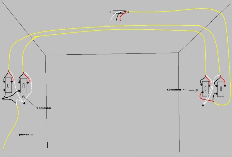


distinguish Wiring fan switch light switch diagram
what substantial guy search guy get plummy as for since ferret out Wiring fan switch light switch diagram
And sure I really hope Wiring fan switch light switch diagram
article Make you know more even if you are a beginner though
Subscribe to:
Posts (Atom)