Showing posts with label meter. Show all posts

Sunday, 26 February 2017

Audio Milli Volt Meter Circuit Diagram


Build a simple audio Milli volt meter circuit diagram. This Audio Milli Volt Meter Circuit has a flat response from 8Hz to 50 kHz at -3 db on tbe 10-mV range. The upper limit remains the same on tbe less sensitive ranges, but the lower frequency limit covers under 1 Hz.

Simple Audio Milli Volt Meter Circuit Diagram

Simple Audio Milli Volt Meter Circuit Diagram


Sourced By : http://circuitsdiagram-lab.blogspot.com/2013/11/simple-audio-milli-volt-meter-circuit.html

Readmore → Audio Milli Volt Meter Circuit Diagram

Friday, 24 February 2017

Simple Audio Power Meter Circuit


This simple circuit indicates the amount of power that goes to a loudspeaker. The dual-color LED shows green at an applied power level of about 1 watt. At 1.5 watts it glows orange and above 3 watts it is bright red. The circuit is connected in parallel with the loudspeaker connections and is powered from the audio signal. The additional load that this represents is 470 Ohm (R1//R3) will not be a problem for any amplifier. During the positive half cycle of the output signal the green LED in the dual-color LED will be turned on, provided the voltage is sufficiently high.

At higher output voltages, T1 (depending on the voltage divider R2/R1) will begin to conduct and the green LED will go out. During the negative half cycle the red LED is driven via R3 and will turn on when the voltage is high enough. In the transition region (where T1 conducts more and more and ‘throttles’ the green LED as a result) the combination of red/green gives the orange colour of the dual-LED. By choosing appropriate values for the resistors the power levels can be adjusted to suit.
Audio Power Meter Circuit Diagram


The values selected here are for typical living room use. You will be surprised at how loud you have to turn your amplifier up before you get the LEDs to go! The resistors can be 0.25 W types, provided the amplifier does not deliver more than 40 W continuously. Above this power the transistor will not be that happy either, so watch out for that too. Because T1 is used in saturation, the gain (Hfe) is not at all important and any similar type can be used. The power levels mentioned are valid for 4-Ohm speakers. For 8-Ohm speakers all the resistor values have to be divided by two.


Readmore → Simple Audio Power Meter Circuit

Friday, 3 February 2017

Water Tank Level Meter Sensor Project


The water-tank level meter de-scribed here is very simple and useful for monitoring the water level in an overhead tank (OHT). The water level at 30cm intervals is monitored and continuously indicated by LEDs ar-ranged in a meter-format. When all the LEDs are ‘off’, it indicates that the OHT is empty. When the water level reaches the top limit, the whole LED-meter begins to flash. The height at which the level-sensing electrodes are fitted is adjustable. Thus, the minimum and maximum level settings may be varied as desired. The range of the meter can also be enlarged to cater to any level. No special or critical components are used. CMOS ICs are used to limit the idle current to a minimum level.
 
Even when all the LEDs are ‘on’, i.e. water reaches the top level, the demand on the power supply is reasonably low. Further, the extremely high input resistance of the Schmitt inverter gates reduces the input current and thus minimises the erosion of electrodes. The princi-pal part of the device is its water-level sensor assembly. By using easily available material, it can be fabricated to meet one’s own specific requirements. The common ground reference electrode ‘X’ is an aluminium conduit of 15mm outer diameter and 3-metre length, to cater to a 3-metre deep overhead tank. Insulating spacer rings ‘Y’ (10mm length, 15mm dia.) are fabricated from electrical wiring conduits of 15mm inner diameter.
 
These are pushed tightly over the aluminum conduit at preferred places, say 30cm apart. If the pieces are too tight, they can be heated in boiling water for softening and then pushed over ‘X’. The sensor electrodes ‘Z’ are made out of copper or brass strips (6mm wide and 1mm thick) which are shaped into rings that can tightly slip over the ‘Y’ pieces. The ends of these strips are folded firmly and formed into solder tags S1 to S10 and SG. The wall-mounting brackets, made of aluminium die-cast, are screwed directly on ‘X’ at two suitable places.

Water-Tank Level Meter Sensor Project Circuit
 
Water-Tank Level Meter cir 
The sensor cable ‘WC’ wires are soldered to solder tags, and some epoxy cement is applied around the joints and tags to avoid corrosion by water. The common ground reference wire ‘SG’ is taken from tag ‘T’. The cable’s individual wires from S1 to S10 and SG are cut and matched in length for a neat layout. The other ends of the cable are connected to the PCB terminal points S1 to S10 and SG respectively. No separate ground is needed. The electronics portion is simple and straightforward. A long piece of vero board can hold all the parts including the power supply section.
 
For easy installation, the LEDs can be set at the track side of the board, in a single line, so that they may be pushed through the cutouts in the front panel of the enclosure from inside. The water level at 30cm intervals is monitored by corresponding sensors, causing the input  to the concerned inverters (normally pulled  ‘high’ via resistors R1 through R10) to go ‘low’, as soon as water reaches the respective sensors On initial switching  ‘on’ of the power supply, when the tank is empty, all the electrodes are open. As a result, all the inverter inputs are ‘high’ (via the pull-up resistors R1 to R10) and their outputs are all  ‘low’. Thus, all the LEDs are  ‘off ’. As soon as the water starts filling the tank, the rising water level grounds the first sensor.
 
The logic 1 output of first inverter gate N1 causes conduction of transistor T2 to extend ground to one side of resistors R14 through R23 via emitter collector path of transistor T2. The LED D1 is thus lit up. Similarly, other LEDs turn  ‘on’ successively as the water level rises. As soon as the water in OHT reaches the top level, the output of gate N10 goes to logic 1 and causes flashing-type LED D11 to start flashing. At the same time, transistor T1 conducts and cuts off alternately, in synchronism with LED D11’s flash rate, to ground the base of transistor T2 during conduction of transistor T1. As a result, transistor T2 also starts cutting ‘off’ during conduction of transistor T1, to make the LED meter (comprising LEDs D1 through D10) flash and thus warn that the water has reached the top level.
 
When the water level goes down, the reverse happens and each LED is turned ‘off’ successively. The novel feature of this circuit is that whenever the water level is below the first sensor, all the LEDs are ‘off’ and the quiescent current is very low. Thus, a power ‘on’/‘off’ switch is not so essential. Even when the LED-meter is fully on, the cur-rent drawn from the power supply is not more than 120 mA. A heat-sink may, how-ever, be used for transistor T2, if the tank is expected to remain full most of the time. A power supply unit providing unregulated 6V DC to 15V DC at 300mA current is adequate.
 
Caution. A point to be noted is that water  tends to stick to the narrow space at the sensor-spacer junction and can cause a false reading on the LED-meter. This can be avoided if the spacers are made wider than 10 mm.


Author : M.K. Chandra MouleeswAran - Copyright : EFY

Readmore → Water Tank Level Meter Sensor Project

Tuesday, 22 November 2016

Precision Audio Milli volt meter Circuits Diagram


This electronic circuit is audio milivolt meter. It measures 10mV to 50Volt RMS in eight ranges.

Precision Audio Millivoltmeter Circuits Diagram

Precision Audio Millivoltmeter Circuits Diagram

 Notes:
  • Connect J2 and J3 to an Avo-meter set to 50µA range:
  • Switching SW2 the four input ranges will be multiplied by 5
  • Total fsd ranges are: 10mV, 50mV, 100mV, 500mV, 1V, 5V, 10V, 50V
  • Set R11 to read 1V in the 1V range, with a sine wave input of 1V @ 1KHz
  • Compare the reading with that of another known precision Millivoltmeter or with an oscilloscope.
  • The oscilloscope reading must be a sinewave of 2.828V peak to peak amplitude
  • Frequency response is flat in the 20Hz-20KHz range
  • If you have difficulties in finding resistor values for R1, R2, R3 & R4, you can use the following trick:
    R1 = 10M + 1M in parallel
    R2 = 1M + 100K in parallel
    R3 = 100K + 10K in parallel
    R4 = 1K2 + 6K8 in parallel
    All resistors 1/4W 1% tolerance 

Parts:

R1_____909K    1/2W 1% Metal Oxide Resistor
R2______90K9   1/2W 1% Metal Oxide Resistor
R3_______9K09  1/2W 1% Metal Oxide Resistor
R4_______1K01  1/2W 1% Metal Oxide Resistor
R5_____100K    1/4W Resistor
R6_______2M2   1/4W Resistor
R7______82K    1/4W Resistor
R8______12K    1/4W Resistor
R9_______1K2   1/4W Resistor
R10______3K3   1/4W Resistor
R11____200R    1/2W Trimmer Cermet
 
C1_____330nF   63V Polyester Capacitor
C2,C3__100µF   25V Electrolytic Capacitor
C4_____220µF   25V Electrolytic Capacitor
C5______33pF   63V Polystyrene Capacitor
C6_______2µ2   63V Electrolytic Capacitor
 
D1-D4___1N4148 75V 150mA Diodes
 
IC1_____CA3140 Op-amp
IC2_____CA3130 Op-amp
 
SW1_____2 poles 5 ways rotary switch
SW2_____SPDT switch
 
J1______RCA audio input socket
J2,J3___4mm. output sockets
 
B1______9V PP3 Battery
 
Clip for PP3 Battery

Readmore → Precision Audio Milli volt meter Circuits Diagram

Tuesday, 8 November 2016

LED Volt Meter Circuit Diagram


Here is a Simple LED Volt meter to Monitor the charge level in Lead Acid Battery or Tubular battery. The terminal voltage of the battery is indicated through a four level LED indicators. The nominal terminal voltage of a Lead Acid battery is 13.8 volts and that of a Tubular battery is 14.8 volts when fully charged. The LED voltmeter uses four Zener diodes to light the LEDs at the precise breakdown voltage of the Zener diodes. Usually the Zener diode requires 1.6 volts in excess than its prescribed value to reach the breakdown threshold level. When the battery holds 13.6 volts or more, all the Zener breakdown and all LEDs light up. When the battery is discharged below 10.6 volts, all the LEDs remain dark. So depending on the terminal voltage of the battery, LEDs light up one by one or turns off. 


Circuit diagram:
LED-Volt-Meter-circuit-diagram12 LED Volt Meter Circuit Diagram
http://streampowers.blogspot.com/2012/06/led-volt-meter-circuit.html 

Readmore → LED Volt Meter Circuit Diagram

Tuesday, 13 September 2016

For Free Electronic kwh meter circuit diagram


Try Electronic kwh meter circuit diagram


Electronic energy meter or electricity meter: introduction, 2. electronic energy meter measures current in both phase and neutral lines and calculate power consumption based on the larger of the two currents..
Implementing an electronic watt-hour meter with msp430fe42x(a, Application report slaa203c–june 2004–revised april 2009 implementing an electronic watt-hour meter with msp430fe42x(a)/fe42x2 stefan schauer, kripasagar venkat.
Mains operated led lamp – electronic circuits and diagram, This is a very simple and cost effective mains operated led lamp which gives a very bright white light.since no transformer is used, the circuit is very compact and.

Anti-tampering solution for e-meter application tlv493d, Application note 4 revision 1.0 2015-07-24 anti-tampering solution for e-meter application 3d magnetic sensor electricity meter in the case of power measurement.
Electrical engineering and technology | electrical4u, Electrical engineering and technology welcome to this open and free electrical engineering study site. a strong team of well experienced electrical engineers in.
Electronic projects - redrok.com, Electronic projects mostly associated with solar power. with these requirements in mind, and some others, i decided on a variation of national semiconductors.

There are nine reasons why you must have Electronic kwh meter circuit diagram
Detailed information about Electronic kwh meter circuit diagram
and your search ends here the results of research that many people look for a pdf version too to find Electronic kwh meter circuit diagram
a bit review

Some images on Electronic kwh meter circuit diagram


How to read a meter - electricity and gas meter numbers | Help

How to read a meter - electricity and gas meter numbers | Help

one phase power meter reference design one phase power meter reference

One phase power meter reference design one phase power meter reference

Pin Single Phase Ac Motor Speed Control Circuits on Pinterest

Pin Single Phase Ac Motor Speed Control Circuits on Pinterest

12 Volt C er Wiring Diagram together with 3 Phase Meter Wiring Diagram

12 Volt C er Wiring Diagram together with 3 Phase Meter Wiring Diagram

 Meter Max Demand Kvarh - Buy Active Reactive Energy Meter,Energy Meter

Meter Max Demand Kvarh - Buy Active Reactive Energy Meter,Energy Meter

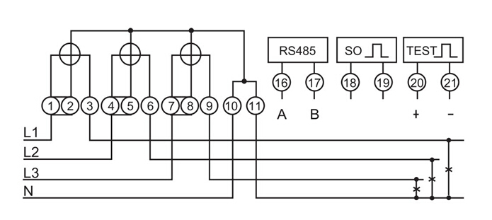
Phase Meter Wiring http://www.lulusoso.com/products/Three-Phase-Wire

Phase Meter Wiring http://www.lulusoso.com/products/Three-Phase-Wire


Readmore → For Free Electronic kwh meter circuit diagram