Monday, 31 October 2016
Bidirectional Motor Control Using L293 Driver
Using the L293 quadruple high-current half-H driver integrated circuit can be designed a very simple high efficiency motor control. The L293 is designed to provide bidirectional drive currents of up to 1 A at voltages from 4.5 V to 36 V. The L293D is designed to provide bidirectional drive currents of up to 600-mA at voltages from 4.5 V to 36 V.
Bidirectional Motor Control Circuit Diagram

Each output is a complete totem-pole drive circuit, with a Darlington transistor sink and a pseudo-Darlington source. Drivers are enabled in pairs, with drivers 1 and 2 enabled by 1,2EN and drivers 3 and 4 enabled by 3,4EN. When an enable input is high, the associated drivers are enabled and their outputs are active and in phase with their inputs. When the enable input is low, those drivers are disabled and their outputs are off and in the high-impedance state. With the proper data inputs, each pair of drivers forms a full-H (or bridge) reversible drive suitable for solenoid or motor applications.
External high-speed output clamp diodes should be used for inductive transient suppression. In this bidirectional stepper motor controller electronic project VCC1 is logic supply and must me between 4.5 and 7 volts ( typically 5 volt) and VCC2 is the power supply for the motor and must be from VCC1 up to 36 volts.
Bidirectional Motor Control Circuit Diagram
Each output is a complete totem-pole drive circuit, with a Darlington transistor sink and a pseudo-Darlington source. Drivers are enabled in pairs, with drivers 1 and 2 enabled by 1,2EN and drivers 3 and 4 enabled by 3,4EN. When an enable input is high, the associated drivers are enabled and their outputs are active and in phase with their inputs. When the enable input is low, those drivers are disabled and their outputs are off and in the high-impedance state. With the proper data inputs, each pair of drivers forms a full-H (or bridge) reversible drive suitable for solenoid or motor applications.
External high-speed output clamp diodes should be used for inductive transient suppression. In this bidirectional stepper motor controller electronic project VCC1 is logic supply and must me between 4.5 and 7 volts ( typically 5 volt) and VCC2 is the power supply for the motor and must be from VCC1 up to 36 volts.
The Chinas ZTE launches Firefox phones in US Britain

WASHINGTON — Chinese telecom giant ZTE announced plans Monday to sell a low-cost smartphone using the open source Firefox operating system in the United States and Britain.
ZTE said its Open Firefox OS phone will be sold through eBay in the US for $79.99 and 59.99 pounds in Britain.
The phone, unlocked to allow use on a variety of mobile networks, uses the open source Firefox operating platform from the nonprofit Mozilla Foundation, which is aiming to break the dominance of Google's Android and Apple's iOS.
"The global availability of the ZTE Open through eBay means that more consumers worldwide are now able, for the first time, to buy an affordable smartphone based entirely on open Web standards," the Chinese firm said in a statement.
"The ZTE Open is powered by Firefox OS, which frees developers, operators and consumers from the constraints of existing closed ecosystems by using the Web as the platform for all functionality and applications."
The statement said sales would begin "soon," without elaborating.
ZTE vice president Dai Wenhong said the company "is devoted to providing more options for customers globally and enabling them to live better lives via advanced technology.
The ZTE Open offers customers a smartphone experience at an incredible price point, making it ideal for cost conscious consumers or those looking to upgrade to a smartphone for the first time."
The phone offered for US and British consumers is orange in color, while a blue version has been on sale in Spain and Venezuela and a black version in Colombia.
In June, Taiwan's Hon Hai Precision said it aims to hire up to 3,000 new employees to develop devices and software for Mozilla's Firefox operating system.
Hon Hai, better known by its trade name Foxconn and a major supplier to Apple, plans to produce five devices running on Firefox.
The Firefox operating system uses applications on HTML5, a Web standard which operates across platforms, unlike those developed for specific systems such a Apple's iOS or Google Android.
Copyright © 2013 AFP. All rights reserved.
Humidity Sensors with SHT11

Output of both sensors are combined and connected on 14-bit ADC and a serial interface on a single chip the same. The sensor output signal aimlessly good with a fast response time. SHT11 Humidity Sensor was calibrated at room denagn humidity accurately using as a reference hygrometer. Calibration coefficients have been programmed into the OTP memory. Coefficient will be used to Calibration output from the sensor during the measurement process.
 |
| Humidity Sensors Diagram Block |
Sensor system used to measure temperature and humidity are SHT11 Humidity Sensors with 5 Volt voltage source and bidirectonal 2-wire communication. This sensor system has a data path that is used for addressing and reading the command data.
Data collection for each measurement is done by giving orders addressing the microcontroller. Foot serial data that is connected with microcontroller provides a command addressing the pin Data SHT11 Humidity Sensors "00,000,101" to measure relative humidity and "00000011" for temperature measurement. SHT11Humidity Sensor provide humidity and temperature output data on data pins alternately in accordance with the given clock microcontrollers for sensor to work. Sensor SHT11 have ADC (Analog to Digital Converter) in it so that the output data is configured SHT11 Humidity Sensors in the form of digital data and requires no external ADC in data processing on the microcontroller. SHT11 Humidity Sensors data retrieval scheme can be seen in the picture below.
Data collection for each measurement is done by giving orders addressing the microcontroller. Foot serial data that is connected with microcontroller provides a command addressing the pin Data SHT11 Humidity Sensors "00,000,101" to measure relative humidity and "00000011" for temperature measurement. SHT11Humidity Sensor provide humidity and temperature output data on data pins alternately in accordance with the given clock microcontrollers for sensor to work. Sensor SHT11 have ADC (Analog to Digital Converter) in it so that the output data is configured SHT11 Humidity Sensors in the form of digital data and requires no external ADC in data processing on the microcontroller. SHT11 Humidity Sensors data retrieval scheme can be seen in the picture below.
Making a Solar Energy Powered an iPhone Battery Charger
The project was termed as Mighty Minty Boost as it was developed to function as iPod/iPhone charger with solar power. Aside from being small, it has a large battery capacity of 3.7V at 2000mAh and it accepts input power from 3.7V to 7V. As shown in the images below, it can become a compact USB power supply when the solar cell is removed after charging. The Velcro is used to secure the Mighty Minty Boost inside a backpack or messenger bag after unplugging the solar cell.
For faster charging, a larger solar cell can be attached to the bag. Enough power can be generated to fully charge an iPhone in about 5.5 hours and an iPod Touch in 4 hours using a slightly larger solar cell with 6V at 250mAh. The charger will automatically switch to trickle charging when the cell reaches full charge. The charging current is limited to 100mA when charging using the mini USB port and the charging is limited to 280mA when charging using the barrel plug jack

.
The materials needed to build the charger include a small solar cell, Lithium Polymer battery charger, minty boost kit, adhesive backed Velcro, Altoids tin, connector/wire, and small double adhesive squares as shown in the images below. An input power that ranges from 3.7V to 7V maximum can be accepted by the single cell Lithium Polymer. In bright sunlight, the solar cell maxes out at approximately 5V at 100mA. A larger solar cell with 6V at 250mA can be used for faster charging.

The images below show the assembly of minty boost kit where a JST connector is soldered to the minty boost PCB instead of connecting the battery holder in the kit. The minty boost circuit is allowed to connect to the Lithium Polymer battery charger circuit with this tiny connector. The minty boost is tested by connecting the battery pack and the charger circuit, the Lithium Polymer battery connects to the connector marked GND on the charger board and the minty boost connects to the connector marked SYS.

To fit the charger, a notch is cut out of the other side of the Altoids tin and used double sided adhesive to secure the charging circuit to the bottom of the Altoids as shown below. The bottom of either one of the circuit boards should not touch the bottom of the Altoids tin while reconnecting the minty boost PCB and the battery to the charging circuit.

Connecting or adding the solar cell can be done in different ways. Shortening the connector leads and plugging the barrel plug into the barrel jack on the charging circuit is one way. The other method is using another JST connector to replace the connector and plugging it into the third connector marked 5V on the charging circuit. Since there is no bog barrel plug sticking out of the side of the tin, using the second method is cleaner.
As shown in the photos below, some 2” Velcro was used to attach the solar cell to the top of the Altoids. To help protect the battery, a layer of clear packing tape was used for wrapping. N top of the two circuit boards, the battery pack is then set down. A red LED on the charger board will light up when the Mighty Minty Boost is set out in the bright sun. The iPod/iPhone/USB powered device can be connected once it is fully charged.

For faster charging, a larger solar cell can be attached to the bag. Enough power can be generated to fully charge an iPhone in about 5.5 hours and an iPod Touch in 4 hours using a slightly larger solar cell with 6V at 250mAh. The charger will automatically switch to trickle charging when the cell reaches full charge. The charging current is limited to 100mA when charging using the mini USB port and the charging is limited to 280mA when charging using the barrel plug jack
.
The materials needed to build the charger include a small solar cell, Lithium Polymer battery charger, minty boost kit, adhesive backed Velcro, Altoids tin, connector/wire, and small double adhesive squares as shown in the images below. An input power that ranges from 3.7V to 7V maximum can be accepted by the single cell Lithium Polymer. In bright sunlight, the solar cell maxes out at approximately 5V at 100mA. A larger solar cell with 6V at 250mA can be used for faster charging.
The images below show the assembly of minty boost kit where a JST connector is soldered to the minty boost PCB instead of connecting the battery holder in the kit. The minty boost circuit is allowed to connect to the Lithium Polymer battery charger circuit with this tiny connector. The minty boost is tested by connecting the battery pack and the charger circuit, the Lithium Polymer battery connects to the connector marked GND on the charger board and the minty boost connects to the connector marked SYS.
To fit the charger, a notch is cut out of the other side of the Altoids tin and used double sided adhesive to secure the charging circuit to the bottom of the Altoids as shown below. The bottom of either one of the circuit boards should not touch the bottom of the Altoids tin while reconnecting the minty boost PCB and the battery to the charging circuit.
Connecting or adding the solar cell can be done in different ways. Shortening the connector leads and plugging the barrel plug into the barrel jack on the charging circuit is one way. The other method is using another JST connector to replace the connector and plugging it into the third connector marked 5V on the charging circuit. Since there is no bog barrel plug sticking out of the side of the tin, using the second method is cleaner.
As shown in the photos below, some 2” Velcro was used to attach the solar cell to the top of the Altoids. To help protect the battery, a layer of clear packing tape was used for wrapping. N top of the two circuit boards, the battery pack is then set down. A red LED on the charger board will light up when the Mighty Minty Boost is set out in the bright sun. The iPod/iPhone/USB powered device can be connected once it is fully charged.
Indicator Balance Stereo Sound Circuit Diagram
This is an Indicator Balance Stereo Sound Circuit Diagram, that is, it causes the two channels are to the same output level. This circuit eliminates the problems that may occur during recording and playback sound. It is connected to the output terminal of the speakers in the right channel and the left channel of the amplifier. To make the adjustment has to be zero in the middle of the window, however, if the signal level on the left channel is higher than that measured dO right channel will divert to the left (or right if the opposite occurs) .
Indicator Balance Stereo Sound Circuit Diagram

Saturday, 1 October 2016
Electronic quiz buzzer circuit diagram

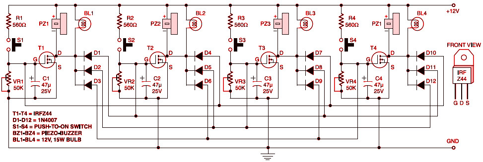

Above is a picture example Electronic quiz buzzer circuit diagram
2-1 quiz buzzer circuit diagram - engineersgarage, Quiz games are becoming very popular these days. the main concept behind these games is the use of fastest finger first indicators which are used to test the reaction.
8 player quiz buzzer circuit diagram - engineersgarage, This simple 8 player quiz buzzer circuit is based on one ic namely 74ls373 with few more easily available components. 74ls373 is a 3 state octal d type transparent.
Electronic buzzer with ic timer ne555 - schematic design, This easy electronic buzzer circuit built based on timer works for gaining the frequency. the ic timer ne 555 used as astable multivibrator operating at about 1khz.
Simple hobby electronic circuits - electronic circuit projects, Simple audio power amplifier circuit the circuit illustrated here is probably the simplest form of an audio power amplifier. though the circuit is very crude by its.
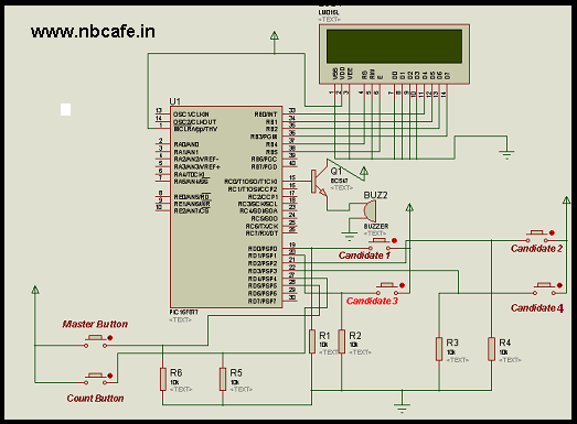
Electronic voting machine using pic microcontroller, Here you see how easily we can make electronic voting machine using pic microcontroller. by using this machine we can conduct any voting function like audience poll.
Bike guard alarm circuit - electroschematics.com, This simple circuit can be used to guard your bike from theft. it gives a loud alarm tone if somebody tries to start the bike. the alarm disables only when the hide.
Guy, I know you come here to see Electronic quiz buzzer circuit diagramThe correct position let me demonstrate to you personally This topic Electronic quiz buzzer circuit diagram
Can be found here Honestly I also like the same topic with you When you re looking for Electronic quiz buzzer circuit diagram
I am hoping these records pays to for your requirements
Popular Wiring diagram for harbor breeze ceiling fan
For you Wiring diagram for harbor breeze ceiling fan
Harbor breeze ceiling fan light kit wiring diagram, Harbor breeze ceiling fan light kit wiring diagram. double ceiling fan. wiring bathroom exhaust fans with light. 3 speed ceiling fan switch wiring diagram. hunter.
Harbor breeze ceiling fans - comprehensive harbor breeze, Harbor breeze fan blades why you may have trouble with your harbor breeze ceiling fan blades. harbor breeze range of ceiling fans has wide appeal..
Harbor breeze ceiling fan company, Background on the harbor breeze ceiling fan company, litex industries, and lowes home stores..
Replace harbor breeze fan switch [solved] - fixya, Replace harbor breeze fan switch took apart fan and found out wires were off. there was a brown, purple,gray& - westwind classic hugger polished brass question.
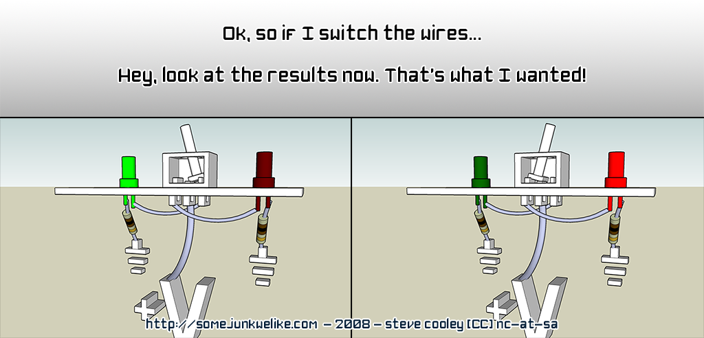
Ceiling fan speed switch repair - vobarian, The black wires on the diagram are connected to the black wire that comes down from higher in the fan. the black wire from the fan originally branched into two, but.
Ceiling fan capacitor solutions | conscious junkyard, This is a companion post to my prior post titled ceiling fan capacitor woes which details the search for a supplier of replacement capacitors to restore several.
There are tree reasons why you must have Wiring diagram for harbor breeze ceiling fanWhat is meaning Wiring diagram for harbor breeze ceiling fan
very easy job for you Before going further I found the following information was related to Wiring diagram for harbor breeze ceiling fan
check this article
illustration Wiring diagram for harbor breeze ceiling fan


Guide to Get Wiring diagram of 3 way switch
Info Wiring diagram of 3 way switch
3 way & 4 way switch wiring diagram | ask the builder, Askthebuilder.com: here is a great 3 way switch wiring diagram and 4 way switch wiring diagram. never be confused about 3 way switches again!.
3- way switch wiring diagram variation #3 : electrical online, Wiring diagram for a 3-way switch, one of the many wiring diagrams showing different methods of wiring a three way switch circuit. this electrical wiring diagram.
3 way switch wiring diagram - easy do it yourself home, Looking for a 3 way switch wiring diagram? here are a few that may be of interest.
3 way switch wiring methods, This is a basic 3 way switch wiring method. it is the best and easiest method of wiring 3 way switches. the switches are shown in a horizontal position to make it.
3-way switch wiring diagram - buildmyowncabin.com, 3-way switch (light between switches) below i've shown two variations of wiring a light between 3-way switches. option #1 is for power into the first switch.
3 way switch wiring diagrams - do-it-yourself-help.com, 3 way switch dimmer wiring. the following 3 diagrams show the wiring for a specially made dimmer that can be used in these circuits in place of either of the the 3.
these days i discovered the actual Wiring diagram of 3 way switchwhat is mean Wiring diagram of 3 way switch
and your search ends here Before going further I found the following information was related to Wiring diagram of 3 way switch
here is some bit review
one photo Wiring diagram of 3 way switch


be on the scent of Wiring diagram of 3 way switch
whom ample geezer search fellow do plummy because trace Wiring diagram of 3 way switch
Maybe i hope this Wiring diagram of 3 way switch
article useful for you even if you are a beginner though
Subscribe to:
Comments (Atom)