Wednesday 30 November 2016

47 Watt BTL Audio Power Amplifier 4 channel


General Description:
The TA8273H is 4 ch BTL audio power amplifier for car audio  application.  This IC can generate more high power: POUTMAX = 47 W as it  is included the pure complementary PNP and NPN transistor  output stage.  It is designed low distortion ratio for 4 ch BTL audio power  amplifier, built-in stand-by function, muting function, and  diagnosis circuit which can detect output to VCC/GND short,  output offset voltage and over voltage input mode. Additionally, the AUX amplifier and various kind of protector  for car audio use are built-in. 
Circuit Diagram:
47 Watt BTL Audio Power Amplifier 4-channel
Datasheet for TDA8273: Download

Readmore → 47 Watt BTL Audio Power Amplifier 4 channel

4 Way Traffic Lights


This circuit produces traffic lights for a "4-way" intersection. The seemingly complex  wiring to illuminate the lights is shown to be very simple.
Readmore → 4 Way Traffic Lights

Tuesday 29 November 2016

3 Band Tone Control Circuit


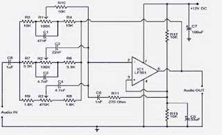
3 Band Tone Control circuit uses an op-amp as an amplifier end. Tone Control circuit is a regulator of tone bass, midrange and treble or 3 band called because it can set the three tones. Filter circuit is applied to the series of "Tone Control 3 band" This type baxandal like the title of this article. 
Results filtering regulator tone or tone control baxandal type is good, because there is no signal level is wasted directly into the ground. Range frequency tones generated from Tone Control 3 band was determined by the configuration of the R and C of the filter section baxandal. As an amplifier on Tone Control The set of three band use traditional IC LF351 has slewrate high and high input impedance. For more details, series 3 Band Tone Control as follows.


Figure Series 3 Band Tone Control


3 band tone control


3 Band Tone Control circuit above using LF351 Op-Amp is used to strengthen the signal after filtering by the filter process baxandal. Level tone Bass, Midrange and Treble settings are determined by potensio R1, R2 and R3. Frequency filter in the circuit above baxandal to 50 Hz bass tone, tone Midrange 1 KHz and 10 KHz for Treble tone.

Readmore → 3 Band Tone Control Circuit

Headset amplifier via USB


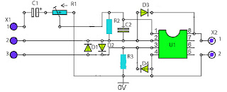
Headset amplifier via USB circuit is a series that is used to add a gain on the headset, which is used on a computer headset. Indeed not only on a computer course in all the headset could also, but in the above circuit voltage to utilize voltage mensupply issued on a PC or laptop via USB. So you need not bother looking for supply voltage, you just take it from USB.
headset amplifier via usb
Part List :

Resistor
R1 = 20K
R2 = 10K
R3 = 10K

Capacitor
C1 = 3u3F 50V
C2 = 100pF

Diode
D1 = 1N4148
D2 = 1N4148
D3 = 1N4148
D4 = 1N4148

IC
U1 = JRC4558

Connector X1
1 = Output
2 = Input
3 = Ground

Connector X2
1 = V+ 5V from USB
2 = Ground From USB

headset amplifier PCB design
PCB design Views

Readmore → Headset amplifier via USB

Low Cost 1 5 to 9 Volts Inverter


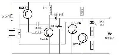
This electronic circuit project is very interesting  and low-cost electronic project,  some electronic circuits we need a 9 volts power supply, but we need to use a battery if that device is mobile. In many cases we don’t have a 9 volts battery or we don’t have enough space to put a 9 volts battery inside the device, so this case we can use a this inverter circuit that will convert 1.5v to 9v to take the place of those expensive 9v batteries.

1.5 to 9 Volts  Inverter  Circuit Diagram:

Inverter

The input voltage for this inverter can be from 1.5 volts, up to 4.5 volts.  When no current is being drawn from the output the current is less than 10mA.

This inverter circuit is very simple requiring few components, but it can be used only for projects that require low current.  The L1 coil must have 60 turns on a 10 mm ferrite slug 15 mm long, using a 0.25 mm diameter enameled wire.


Readmore → Low Cost 1 5 to 9 Volts Inverter

Monday 28 November 2016

Mobile Automotive Stereo Player Circuit diagram


Mobile Automotive Stereo Player Circuit diagram. Using a mobile phone while driving is dangerous. It is also against the law. However, you can use your mobile phone as a powerful music player with the help of a stereo power amplifier. This does away with the need of a sophisticated in-dash car music system. Most mobile phones have a music player that offers a number of features including preset/manual sound equalisers. They have standard 3.5mm stereo sockets that allow music to be played through standard stereo headphones/sound amplifiers. Nokia 2700 classic is an example. 

Mobile Automotive Stereo Player Circuit diagram :
Circuit of mobile car stereo player
Mobile Car Stereo Player Circuit Diagram

A car audio amplifier with 3.5mm socket can be designed and simply connected to the mobile phone output via a shielded cable with suitable connectors/jacks (readymade 3.5mm male-to-male connector cable is a good alternative). Fig. 1 shows the circuit of car stereo player. It is built around popular single-chip audio power amplifier TDA1554Q (IC1). The TDA1554Q is an integrated class-B power amplifier in a 17-lead single-in-line (SIL) plastic power package. 

IC TDA1554Q contains four 11W identical amplifiers with differential input stages (two inverting and two non-inverting) and can be used for single-ended or bridge applications. The gain of each amplifier is fixed at 20 dB. Here it is configured as two 22W stereo bridge amplifiers. The amplifier is powered from the 12V car battery through RCA socket J2. Diode D1 protects against wrong-polarity connection. LED1 indicates the power status.
Stereo Jack :
3.5mm stereo socket and (b) 3.5mm
(a) 3.5mm stereo socket and (b) 3.5mm Stereo Jack
Connect stereo sound signal from the 3.5mm headset socket of the mobile phone to audio input socket J1. When you play the music from your mobile, IC1 amplifies the input. The output of IC1 is fed to speakers LS1 and LS2 fitted at a suitable place in your car. Electrolytic capacitor C5 connected between pin 4 of IC1 and GND improves the supply-voltage ripple rejection. Components R2 and C4 connected at mute/standby pin (pin 14) of IC1 eliminate the switch on/off plop. The circuit is quite compact. A good-quality heat-sink assembly is crucial for IC1. Fig. 2 shows the stereo socket and stereo jack.
Proposed enclosure Proposed enclosure

Assemble the circuit on a general-purpose PCB and enclose in a suitable cabinet. Small dimensions of the power amplifier make it suitable for being enclosed in a plastic (ABS) case with vent holes. Signal input socket, speaker output terminals, on/off switch, indicator, fuse holder and power supply socket are best located on the front panel of the enclosure as shown in Fig. 3. 

Author : T.K. Hareendran - Copyright : EFY

Readmore → Mobile Automotive Stereo Player Circuit diagram

Temperature Detector For Fan Controller


The fan controller circuit for the Titan 2000 and other AF heavy-duty power amplifiers, has an output that sets a voltage if the fan controller reaches the end of its range. Since the controller responds to temperature, this signal is seen by the amplifier protection circuitry as an over temperature indication. The disadvantage of this output is that the maximum voltage for the fans is not constant, but depends on the load (number of fans, defective fans) and the mains voltage. This variation is caused by the fact that the supply voltage for the output stage is taken directly from the filtered transformer voltage.

Maximum Temprature Detector For Fan ControllerIf the fans should fail, for example, the maximum temperature limit would lie at a considerably higher level than the desired value. The accompanying circuit, which compares the magnitude of the fan voltage to a fixed reference value, has been developed to allow the maximum temperature to be reliably detected. This circuit is tailored for 12-V fans. The reference voltage is generated by the ‘micro power voltage reference’ D1 and the FET T1, which is wired as a current source. These components are powered directly from the applied fan voltage. The current source is set up to deliver approximately 50µA.

D1 can work with as little as 10µA. The supply voltage for the IC is decoupled by R10, C3 and C4, with D4 providing over voltage protection. A maximum supply voltage of 16 V is specified for the TLC271. This opamp works with a supply voltage as low as 3 V and can handle a common-mode voltage up to approximately 1.5 V less than the positive supply voltage. Accordingly, 1.2 V has been chosen for the reference voltage. The fan voltage is reduced to the level of the reference voltage by the voltage divider R2–R3–P1. The limits now lie at 11.2 V and 16.7V.

If you find these values too high, you can reduce R2 to 100 kΩ, which will shift the limits to 9.5 V and 14.2 V. The output of the voltage divider is well decoupled by C2. A relatively large time constant was selected here to prevent the circuit from reacting too quickly, and to hold the output active for a bit longer after the comparator switches states. A small amount of hysteresis (around 1 mV) is added by R4 and R5, to prevent instability when the comparator switches. D2 ensures that the magnitude of the hysteresis is independent of the supply voltage. Two outputs have been provided to make the circuit more versatile.

Output ‘R’ is intended to directly drive the LED of an optocoupler. In addition, transistor T2 is switched on by the output of the opamp via R7 and R8, so that a relay can be actuated or a protection circuit triggered using the ‘T’ output. The high-efficiency LED D3 indicates that IC1 has switched. It can be used as a new ‘maximum’ temperature’ indicator when this circuit is added to the fan controller. The circuit draws only 0.25 mA when the LED is out, and the measured no-load current consumption (with a 12.5V supply voltage) is 2.7 mA when the LED is on.

Resistors:
  • R1 = 22kΩ
  • R2 = 120kΩ
  • R3 = 10kΩ
  • R4,R6 = 1kΩ
  • R5 = 1MΩ
  • R7,R8 = 47kΩ
  • R9 = 3kΩ9
  • R10 = 100Ω
  • P1 = 5kΩ preset
Capacitors:
  • C1,C3 = 100nF
  • C2 = 100µF 25V radial
  • C4 = 47µF 25V radial
Semiconductors:
  • D1 = LM385-1.2
  • D2 = BAT85
  • D3 = high-efficiency-LED
  • D4 = zener diode 16V/1W3
  • T1 = BF245A
  • T2 = BC547B
  • IC1 = TLC271CP
Miscellaneous:
  • K1 = 2-way PCB terminal block, raster 5mm
  • K2 = 3- way PCB terminal block, raster 5mm

Readmore → Temperature Detector For Fan Controller

Sunday 27 November 2016

An Electronic Watering Can


Summertime is holiday time but who will be looking after your delicate houseplants while you are away? Caring for plants is very often a hit or miss affair, sometimes you under-water and other times you over-water. This design seeks to remove the doubt from plant care and keep them optimally watered.

The principle of the circuit is simple: first the soil dampness is measured by passing a signal through two electrodes placed in the soil. The moisture content is inversely proportional to the measured resistance. When this measurement indicates it is too dry, the plants are given a predefined dose of water. This last part is important for the correct function of the automatic watering can because it takes a little while for the soil to absorb the water dose and for its resistance to fall. If the water were allowed to flow until the soil resistance drops then the plant would soon be flooded.

Circuit diagram :

An Electronic Watering Can-Circuit Diagram

An Electronic Watering Can Circuit Diagram

The circuit shows two 555 timer chips IC1 and IC2. IC1 is an astable multivibrator producing an ac coupled square wave at around 500 Hz for the measurement electrodes F and F1. An ac signal reduces electrode corrosion and also has less reaction with the growth-promoting chemistry of the plant. Current flowing between the electrodes produces a signal on resistor R13. The signal level is boosted and rectified by the voltage doubler produced by D2 and D3. When the voltage level on R13 is greater than round 1.5 V to 2.0 V transistor T2 will conduct and switch T3. Current flow through the soil is in the order of 10 µA.

T2 and T3 remain conducting providing the soil is moist enough. The voltage level on pin 4 of IC2 will be zero and IC2 will be disabled. As the soil dries out the signal across R13 gets smaller until eventually T2 stops conducting and T3 is switched off. The voltage on pin 4 of IC2 rises to a ‘1’ and the chip is enabled. IC2 oscillates with an ‘on’ time of around 5 s and an ‘off’ time (adjustable via P2) of 10 to 20 s. This signal switches the water pump via T1. P1 allows adjustment of the minimum soil moisture content necessary before watering is triggered.

The electrodes can be made from lengths of 1.5 mm2 solid copper wire with the insulation stripped off the last 1 cm. The electrodes should be pushed into the earth so that the tips are at roughly the same depth as the plant root ball. The distant between the electrodes is not critical; a few centimetres should be sufficient. The electrode tips can be tinned with solder to reduce any biological reaction with the copper surface. Stainless steel wire is a better alternative to copper, heat shrink sleeving can used to insulate the wire with the last 1 cm of the electrode left bare. Two additional electrodes (F1) are con nected in parallel to the soil probe electrodes (F). The F1 electrodes are for safety to ensure that the pump is turned off if for some reason water collects in the plant pot saucer. A second safety measure is a float switch fitted to the water reservoir tank.

When the water level falls too low a floating magnet activates a reed switch and turns off the pump so that it is not damaged by running with a dry tank. Water to the plants can be routed through closed end plastic tubing (with an internal diameter of around 4 to 5 mm) to the plant pots. The number of 1 mm to 1.5 mm outlet holes in the pipe will control the dose of water supplied to each plant. The soil probes can only be inserted into one flowerpot so choose a plant with around average water consumption amongst your collection. Increasing or decreasing the number of holes in the water supply pipe will adjust water supply to the other plants depending on their needs. A 12 V water pump is a good choice for this application but if you use a mains driven pump it is essential to observe all the necessary safety precautions.

Last but not least the electronic watering can is too good to be used just for holiday periods, it will ensure that your plants never suffer from the blight of over or under-watering again; provided of course you remember to keep the water reservoir topped up…

Author : Robert Edlinger - Copyright : Elektor


Readmore → An Electronic Watering Can

Inverter 12V to 115V with 25 W power output


Low power inverter schematic are only use 9 components , one of which IC 556 , TIP120 NPN Darlington transistor.And turns 10 to 16 Vdc into 60 HZ, output 115 V square-wave power to operate ac equipment up to 25 W. In the circuit first ic originally hires as a timer chip m for stabilizatiom oscilator with components R1 and C1 setting frequency oscilator. Then the two transistor driver, drive the transformer push-pull fashion, When one transistor is biased on , the other circuit cut-off . The transformer is a 120V/18Vct unit that is connected backwards, so that it steps the voltage up rather than down. Oscilator circuit operates from about 4 to 16 V for  stable output.
inverter ac to dc
 Part List :
R1 = 1K
R2 = 12K
R3 = 1K
R4 = 1/4W
C1 = 1uF
IC = 556
Q1 = TIP120
Q2 = TIP120
T1 = 120V 18VCT
Readmore → Inverter 12V to 115V with 25 W power output

Read Only Memory


Memory group called Read Only Memory also has characteristics that match the name. Existing data in ROM, this is data that has been entered by the manufacturer. The data already contained in it can not be changed again through the normal process, and can only be read only. There are pieces of data in ROM is used for the identity of the computer itself. It is stored in the BIOS (Basic Input Output System). There are also data contained in this module was first accessed by a computer when it boots. Sequences contained in this module and are accessed the first time when the computer is turned on is called bootstrapping.


In this bootstrap process, carried out some instructions such as checking the internal components supporting the work of at least one computer system, such as checking ALU, CU, BUS supporter of the motherboard and processor, check the main BIOS, check the graphics card BIOS, check the Memory Module, check for the presence Secondary Storage which can be a floppy disk, hard disk, or CD-ROM drive, then just check the MBR (Master Boot Record) of the storage media designated by the BIOS (in the Boot Sequence). The following will be discussed types of ROM and its development.

PROM (Programmable ROM)
ROM provides an opportunity for users to modify data stored by default. A device called PROM programmer in charge of "burn" (burn in) this chip. With a strong electric current bit location will burn and showed a value (0 or 1). After going through the process burningin, this PROM can no longer be changed contents.

EPROM (Erasable Programmable ROM)
This chip is the development of PROM. Only, this EPROM can be erased its previous contents using ultraviolet light. These rays pass through a gap in the collection of chips. Thus, the charge stored can be released. In other words, EPROM can be erased with ultraviolet light and reprogrammed electrically.

EEPROM (Electrically Erasable Programmable ROM)
This chip is not much different from the EPROM, EEPROM data but can be removed without the use of ultraviolet light. Just use electrical pulses (electrical pulses). Types of ROM such as PROM, EPROM and 

EEPROM memory is classified into stable (nonvolatile memories). That is, these three types of ROM memory will keep its data even when not fed by electrical current. In development, the EEPROM chip has been used for the BIOS of a motherboard. By using the technique of "flash", the contents of the BIOS can be made later (update). However, the danger of flashable BIOS is all people can change the contents, including viruses. If you have been changed by a virus, then used a computer motherboard that will not be used again.

Readmore → Read Only Memory

Saturday 26 November 2016

TDA2005 2 X 20 Watt Power Amplifier


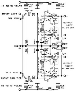
This time, there is a series of audio amplifer 20W as well, but using IC TDA 2005 as a series of his base amplifier.
The series of 2x20 Watt Audio Power Amplifier using TDA2005 can you see in the picture below.


TDA2005 2 X 20 Watt Power Amplifier


Technical Data:

Performance of TDA2005M: (for this circuit); At 4.14 V supply voltage: 2 x 20 watts (stereo) into 4 Ohms.
Distortion: Approx. 0.2% at 4 Watts into 4 ohm load.

Frequency Range: Approx. 20 Hz to 22 KHz.

Input Sensitivity: Approx. maximum 150 mV rms. .

Power supply: + 8 to 18 volts, approx. 3.5 Amps maximum per channel.
Readmore → TDA2005 2 X 20 Watt Power Amplifier

Audio Mixer


General Description:
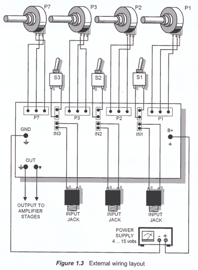
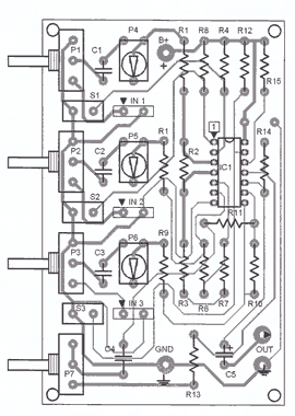
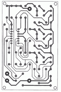
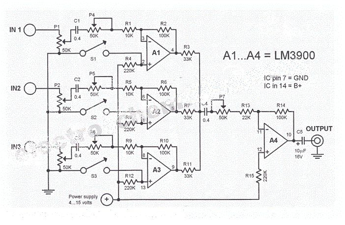
A new audio mixer circuit uses an LM3900 IC but is not a profesional audio dj mixer. The IC houses four integrated Norton amplifiers. The advantage of using the four op amps is that they only need a single power supply. Since this amplifier circuit is current controlled, the DC bias is dependent on the feedback coupling.The schematic diagram shows inverting AC-Norton amplifiers. The DC output must be set at 50 percent of the power supply. In this case, a maximum output can be achieved without distortion (also called symmetrical limitation through overdrive).In designing this mini audio mixer circuit diagram you can freely choose the value of the resistor R2 (100k in the mixer schematic). Set the AC voltage amplification factor through the ration of R2/R1. To set the amplifier gain correctly, choose the value of R4=2R2 (double the value of R2).Diagram 1.0 shows the 3-channel sound mixer circuit using three Norton-opamps. The input levels can be set by potentiometers P1 or P3. Furthermore, each input level can be trimmed with the help of trimmers pots P4 to P6 to adapt each input to the source. The resistors at the non-inverting inputs of the opamps work as DC bias and set the DC output at 50 percent of the power supply for this powered audio mixer. All three input signals are summed by the fourth opamp A4 through the resistors R3, R7 and R11. The commom volume level is cotrolled through the potentiometer P7. You can switch an input channel on or off through the switches S1 and S3. An input channel is turned off when its switch is closed. It is also possible to replace these mechanical switches with transistor gates. By doing so, you can build an analog multiplexer circuit that can be easily expanded by several inputs.
Circuit Diagram and PCB:
Audio Mixer Circuit Diagam

Audio Mixer Circuit Diagam
Audio Mixer Circuit digram

Audio Mixer Circuit Diagam
Audio Mixer layout

PCB Audio Mixer
PCB Audio Mixer


Readmore → Audio Mixer

Symmetric Output for USB Audio DAC


This simple adapter circuit is specially intended for use with the USB Audio DAC published in this website elsewhere. With an easily implemented modification, it is possible to make the output of the D/A converter pseudo-symmetric, so that it can be connected to professional equipment having XLR line inputs. This will do even more justice to the high quality of the USB Audio DAC. The modification actually amounts to just adding a single resistor (R11a) and changing the value of the existing resistor at the output of the audio DAC (R11) from 100 Ωto 68Ω. Components C14 and R12 remain unchanged. It is not difficult to make this change on the printed circuit board of the audio DAC, but a bit of improvisation is necessary. After replacing R11 with a 68-Ω version, unsolder R12 and connect R11a in series with it. Bring out the junction of these two resistors to act as the signal return connection (pin 3 of the XLR socket). The same operation must also be carried out on the right channel, where the affected resistors are labelled R16, R16a and R17.


Readmore → Symmetric Output for USB Audio DAC

Friday 25 November 2016

Geiger Counter Uses Cockroft Walton Multiplier


The recent tsunami in Japan and the on-going calamity with the Fukushima nuclear power plant has apparently greatly increased sales of radiation meters, not only in Japan but elsewhere around the world. This device will allow an estimation of the level of radioactivity, being sensitive enough for background radiation monitoring or to provide an estimation of the level of radioactivity from sample objects such as Thorium gas mantles in LPG lamps. The circuit is compatible with several Geiger Muller tubes and three types of indication are provided: the good old-fashioned audible click with each discharge, a flashing LED or an analog meter providing a rough average of radiation levels.


Geiger Counter Uses Cockroft-Walton Multiplier

A normal background count in New Zealand with the smaller GM LND712 tube is around 30 counts per minute, while the larger and more-sensitive LND7312 pancake tube will count about four times this figure. Both GM tubes will detect alpha, beta and gamma radiation. Unless the tube is “filtered”, there is no way of knowing just what type of radiation is being detected, although a rough guess can be made. Alpha particles will be stopped by placing a sheet of paper between the tube and the source, Beta particles (electrons) will be stopped with a few layers of aluminium foil and the more lively Gamma rays will need a layer of lead.

The circuit provides a regulated 500V supply for the Geiger Muller tube. This voltage places the tube into its linear operating mode so that a discharge inside the tube will occur when a particle enters through the mica window of the tube and causes the gas to ionise. The very short pulse produced is stretched and used to signal that a discharge has occurred. The power supply consists of an oscillator and small transistor driving the 6V secondary of a 240VAC mains transformer. The stepped up output of the transformer is fed to a Cockroft-Walton voltage multiplier consisting of diodes D3-D7 and the associated 47nF 630V metallised polyester capacitors.

IC1 is a 40106 Schmitt trigger inverter and IC1a is connected as an oscillator running at several hundred hertz. This is buffered by IC1b and fed to the base of NPN transistor Q1 which then drives the abovementioned transformer. IC1c acts as an error amplifier to regulate the high voltage fed to the GM tube. A portion of the DC voltage produced at the junction of diodes D4 & D5 is monitored by a voltage divider consisting of the 4.7MO and 47kO resistors, in combination with trimpot VR1. When the voltage from D5 is below the positive threshold of IC1c, its output will be high and IC1a will be able to oscillate. Hence, the oscillator will pulse on and off, to maintain the 500V set by VR1.

Each time there is a discharge in the GM tube, the resultant current triggers the BT149 SCR which discharges the associated 100nF capacitor and thereby acts as a pulse stretcher to drive the three remaining inverters in IC1. These in turn drive a high-brightness red LED (LED1), a piezo transducer and an analog metering circuit which is based on an old VU meter movement with a scale graduated in counts/minute. The current drain of the circuit is 10mA and a small 9V battery should run the counter for many hours. Warning: do not touch the window of the GM tube. These are very fragile and made of very thin mica, to allow the low-energy alpha particles to pass through. With the LND 712, 200 counts per minute is roughly equivalent to 0.3 micro-seiverts.

Readmore → Geiger Counter Uses Cockroft Walton Multiplier

Thursday 24 November 2016

Experimental Hall Sensor


Hall sensors can of course be purchased but making them yourself is far more interesting (and satisfying)!
According to the theory the crucial thing is to use a touch layer that’s as thin as possible; the length and width are unimportant. An ‘obvious’ starting point for our trials would be copper, which in the form of printed circuit board material is easy to find and handle. Copper-clad board may be obvious but not ideal, because it has a very weak Hall constant.

Nevertheless we should be able to use it to demonstrate the Hall effect by using very powerful magnets in our sensor.To achieve detection we need the highest possible level of amplification. In the circuit shown here the voltage amplification is set by the relationship of the two feedback resistors of the first op-amp. With the values given (2.2 MΩ and 330 Ω) produce a gain of 6,667.

Experimental Hall Sensor Circuit Diagram :
Experimental Hall-Sensor-Circuit Diagram
This also creates a convenient bridge connection for taking measurements. The trimmer potentiometer allows fine adjustment. With zero set ting that’s accurate to within millivolts we could use this test point to measure Hall voltages of well below a microvolt. Finally in this way we could also measure the flux density of a magnet.

Copper has a Hall constant of AH= –5.3·10-11m3/C. The thickness of the copper layer is d = 35 µm. The Hall voltage then amounts to:VH= AH× I × B / d

When the field B= 1 T and current I= 1 A a Hall voltage of VH= 1.5 µV is produced. The6,667-fold gain then achieves a figure of 10 mV. The circuit thus has a sensitivity of 10 mV per Tesla. That said, adjusting the zero point with P1 is not particularly easy. The amplifier has a separate power supply in the form of a 9 V battery (BT1). To take measurements we connect a lab power supply with adjustable output current (BT2) to the Hall sensor (the copper surface) and set the current flowing through the sensor to exactly 1 A. Then the zero point must be adjusted afresh.

Next we place a strong Neodymium magnet below the sensor. The output voltage of the circuit should now vary effectively by several millivolts. Note that there are several effects that can influence the measurements we take. Every displacement of the magnet will pro-duce an induction voltage in the power feed wires that is significantly greater than the Hall voltage itself. Every time you move the magnet you must wait a while to give the measurements time to stabilise. With such small voltage measurements problems can also arise with thermal voltages due to temperature variations. It’s best not to move and inch — and to hold your breath as long as possible!

Author : Burkhard Kainka - Copyright : Elektor

Readmore → Experimental Hall Sensor

A Simple Inverter 12 220 V


A simple inverter transformer used by loadable and allow (to increase efficiency ) change the frequency 50/60 Hz .

This simple drive can serve as a source of voltage 230V/50Hz for appliances to power by the transformer used , which can be compact fluorescent lamp with ballast choke DZ series and classic scooters , razors, power televisions and other consumer electronics , backup gas boilers during a power failure . and current clip . Are used both in the home and at the cottage, ala especially campers , boat and everywhere where there is no grid 230 . 

Simple Inverter 12/220 V  Circuit Diagram

 Inverter 12/220 V Circuit Diagram

The connection is very simple. As a 50Hz square wave generator is used monostable flip-flop 4047 working in astable mode. The outputs 10 and 11 are available in -phase output pulses , which are driven by four MOS switches involved in the bridge connecting alternately winding transformer 10V to 12V power supply . If the output 10 IO1 H level , the transistor T3 is switched conductivity N, while the output is 11 L level at which the transistor T2 is switched conductivity P.

 After flipping levels at outputs 10 and 11 are provided transistors undone and the transistors T1, T4. The presence of signals produced 230V glow . PR1 switch can change the frequency of the generator from 50Hz to 60 Hz . To power all these appliances is not necessary to use a crystal oscillator 50Hz . With the values ​​of components RC oscillator on pins 1 , 2 IO1 the accuracy and frequency stability about 2 %, which for all these applications is sufficient .

Increasing the frequency to 60Hz can be achieved by a significant reduction in the current drawn from the battery without a load connected - to a half . At this frequency also can be partially small increase speed of asynchronous motors . (Motorcycle without carbon.) The frequency 60Hz is possible to operate all of the above appliances and inverter achieves higher efficiency. Frequency of 60Hz is used in USA , Japan and many other countries.


 Inverter 12/220 V Circuit Diagram
12/220 V Circuit Diagram

Design - for PCB mount 2pcs first wire connection , the first located at POJ1 , one of IO2 . Pinholes transistors is necessary to ream bur A1mm to fuse strips A1.2mm , four holes for mounting transistors A3.2mm . These drill holes are accompanied by dural L cooler and side joints with traces holes to mount transistors. Traced These holes are also drilled A3.2mm .
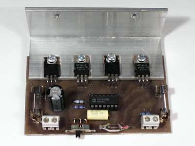
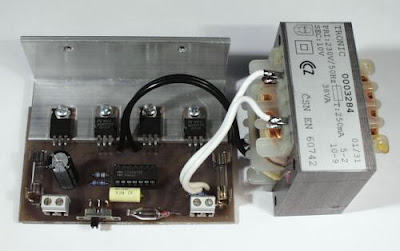
The transistors are bent pins 90 °. Under the screw heads must stringing plastic insulating washers and over mica , which is suitable to coat on both sides with silicone grease to improve thermal conductivity , the transistors screwed to the heat sink and plate as shown. Strengths of the PCB Can going through here , despite the current 4A. The integrated circuit is in the slot. Fifth, the transformer terminals to board pieces Lanka . On pins 9-10 transformers use wire and at least 1 mm. Power drive parameters can be easily increased in exchange for a larger transformer , which has a transfer 230V/10-12V .

No problems were tested transformer with an output of 200W . Unwinding the secondary winding of 12V to 10V achieved performance of about 160W . Even better performance , higher efficiency and lower no-load current consumption can be achieved with toroidal transformers . At higher outputs must be left to the radiator bolted effective cooling fins , with 40W transformer contained in the kit is L cooler at full load temperature of about 40C ° . The drive gives the open circuit voltage of about 260V , which is not necessary to worry about. The connected load voltage is reduced to the optimum .

I have enabled grid voltage fluctuation tolerance + / -10 %, which is from 207V to 253V . The drive is suitable for security build in a plastic box . It should be noted that the transformer , fuse , doutnavce and the output terminal voltage is dangerous .

Circuit Diagram PCB

Achieved characteristics :

Transformer 40W included in the kit:
Open circuit voltage of 260V
current consumption of 400 mA
voltage across the lamp 25W 230V
consumption at 25W load 2.5 A
voltage across the lamp 40W 220V
consumption under load 40W 3,8 A

Other transformer with an output of 100W/230V/10V
Open circuit voltage of 270V
current consumption of 800 mA
voltage across the lamp 40W 225V
consumption under load 40W 3,6 A
voltage across the lamp 60W 210V

consumption under load 60W 4,8 A


Readmore → A Simple Inverter 12 220 V

Off Hook Telephone Line Indicator


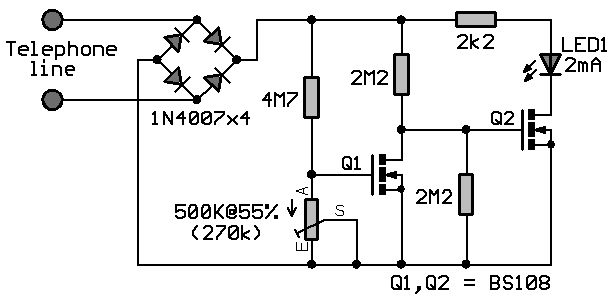
The circuit is designed to connect in parallel with the telephone line, to monitor and detect if any telephone in the same line is busy, with the indication of the LED and which is self-powered so that it does not provide any load on a telephone line.

Light Emitting Diode (LED) – a semiconductor diode that is commonly a source of light when electric current pass through it Metal Oxide Semiconductor Field Effect Transistor (MOSFET) – a device utilized for switching and amplification of signals BS108 – a 250 mA and 200 Volts small signal MOSFET designed for high voltage, high speed switching applications such as relay drivers, CMOS logic, line drivers, TTL or microprocessor to high voltage interface and high voltage display drivers Diode Bridge – also known as bridge rectifier which has four diodes arranged in a bridge configuration where the output voltage has the same polarity with either polarity of the input voltage 1N4007 – a general purpose plastic rectifier with reverse voltage from 50 Volts to 1000 Volts and forward current of 1.0 Ampere

When none of the telephone lines is in use or on-hook, the voltage across the line is around 48V. In this state, the gate of transistor Q2 is shorted to its source during the conduction of Q1. This causes the LED to be disabled while Q2 is turned OFF. When one telephone extension along the telephone line changes to off-hook or in use condition, a voltage drop from 5V to 15V is detected. This will in turn cause Q1 to turn OFF because of the very low voltage across the gate of Q1 which is equal to 6% of the line voltage. Transistor Q2 then will be biased at around half of the line voltage.

Off-Hook Telephone Line Indicator Circuit Diagram


Off-Hook Telephone Line Indicator

 The sudden line drop of voltage triggers Q2 to light up the LED that will give a sign that the line is in use. Using the same line, the circuit is unseen with other telephone devices. A current-limiting resistor is used to maintain the low current of LED1 while the local telephone line parameters dictate the variation of other component’s values. The power of the circuit is provided by the telephone line. Other voltage protection may be used with some reliable design in addition to the current-limiting resistor. This is important to avoid any grounding effects from conducting surfaces within the circuit.

To ensure that transistor Q1 is fully biased while the line is free or not in use where LED1 is OFF, a 500K ohm MOSFET trimmer is used for the desired adjustment. A MOSFET is a three-terminal semiconductor component with a conducting channel in its output and a built-in capacitor at its input. To increase the values of any of the two resistors connected to the gate of Q2, a 200V MOSFET can be used in the place of Q2 if BS108 is not available. However, plain transistors like the bipolar junction can be used but with lower values to allow greater currents to pass through the line that is not in use. The bridge rectifier comprising of four 1N4007 diodes are performing the conversion of AC input into DC output.

MOSFET can function in two ways. The first is known as depletion mode wherein the channel shows its maximum conductance in the absence of a voltage on the gate. The second way that the MOSFET can function is known as enhancement mode wherein the device is not conducting even in the absence of a voltage on the gate because no channel is produced. A channel is being created with the application of a voltage to the gate. To generate better conductivity, greater voltage to the gate is required.

MOSFET drivers are applied in electronic motor control for different types of motors. Also, they are specifically used with long duty cycles, high operating frequency above 200 KHZ, lower output power, and wide load variations. The largest application of MOSFETs are the switched mode power supplies and in battery charging applications. In transducer drivers for high power devices such as light bulbs and motors, large current output with a small input is provided by MOSFETs. Since they are more non-linear than BJTs while producing less distortion, they can be utilized with Hi-Fi amplifiers. In constructing integrated circuits, MOSFETs are very useful since they can be made very compact. Although MOSFETs can get damaged by static electricity at higher voltages, they still provide several advantages as compared to other transistors which include faster switching time than BJT, lower losses than BJT, very small switching current, and least effects of temperature.

This telephone line indicator does not only tell when a telephone line is in use if a plurality of telephones are all setup to the same telephone line, but also prevents interruptions during personal calls. Additionally, it can also help to prevent costly and unwanted disruption of modem calls and fax, it alerts a person when a call is done and the phone is free to use, and the LED light indicates the line is in use.

To avoid any injury, it is a prerequisite to take extra precautionary measures when connecting any circuit to the telephone lines, which can produce life-threatening voltages during normal operation. During a lightning storm, it is better to keep distance from telephone lines.. Legal aspects are imposed in different countries for connecting things to telephone lines. The circuit should be better built with a plug-in cord for easy removal in case of fault occurrences. Otherwise, it would be best to consult a licensed telephone operator.

Readmore → Off Hook Telephone Line Indicator

Speech Filter


Description 
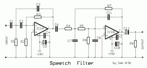
The human speech apprehend a small area of frequencies, that is extended from 300HZ until 3KHZ. This spectrum is also internationally recognized for the transmission of speech via telecommunications networks. This is also the mainer use of this circuit, one and it can be used in uses that we needed this concrete spectrum of frequencies, rejecting the spectrum on and under what, making comprehensible the speech. The circuit is constituted by two active units, filters of second class (calculated for critical damping). The first filter round the IC1A rejects the low frequencies (under 300 HZ) [high pass] and the second IC1B high (above 3KHZ) [low pass], composing thus a total filter band pass of area (300HZ-3kHZ). In order to has good yield the filter, as with all the filters, it should are used resistances metal film 1% and capacitors polysteryne. 
Circuit diagram
Part List
  • R1= 120Kohm
  • R2= 100Kohm
  • R3= 470Kohm
  • R4-7= 8.2Kohm
  • R5= 6.8Kohm
  • R6= 33Kohm
  • R7= 150Kohm
  • R8= 47Kohm
  • C1-2-8= 2.2nF 100V polystyrene
  • C3= 150pF
  • C4-9= 100nF 100V
  • C5-10= 47uF 25V
  • C6= 100nF 100V polystyrene
  • C7= 560pF
  • C11= 150pF
  • C12= 10uF 25V
  • IC1= TL072 
 Source http://users.otenet.gr/~athsam/speetch_filter.htm

Readmore → Speech Filter

LM350 12 Volt Battery Charger


The battery circuit scheme is designed as a source of constant voltage with negative temperature coefficient. Transistor Q1 (BD 140) is used as a temperature sensor. transistor Q2 is used to prevent the battery from discharging through R1 when electrical power is unavailable. Charging circuit is designed based on the LM350 voltage regulator IC. The output voltage of the charger can be adjusted between 13-15 V by varying the POT R6.


LM350 will try to keep the voltage drop between the input pin and output pin at a constant value of 1.25V. So there will be a constant current flow through resistor R1. Q1 act here as a temperature sensor with the help of R6/R3/R4 components that are more or less controls the base current of Q1. As connection emitter / base of transistor Q1, the same as other semiconductors, containing the temperature coefficient of-2mV / ° C, the voltage output will also show a negative temperature coefficient. This one is just a factor of 4 large, because the variation of the emitter / base of Q1 is multiplied by a factor of division P1/R3/R4. This leads to some-8mV / ° C. LED will light whenever power is available.

Readmore → LM350 12 Volt Battery Charger

Tuesday 22 November 2016

Mini Blender blends clean with effect


Readmore → Mini Blender blends clean with effect

LBL Activated Remote Control Circuit Diagram


This is the simple Laser Beam Light Activated Remote Control Circuit Diagram. The following post illustrates a simple light toggled/operated remote control circuit, which can be activated by an ordinary flashlight or more effectively through a laser beam unit (key chain type).

 LBL Activated Remote Control Circuit Diagram


The circuit idea may be understood with the below mentioned points:

  1. Transistor T1 alnog with R3, C6 and the LDR itself forms a simple light sensor stage.
  2. The LDR is connected across the base of the transistor and the positive supply such that when light falls over the LDR, T1 receives the required base bias and conducts.
  3. When T1 conducts, the high potential at pin 14 of IC1 is pulled to logic low. However since a logic low wouldn't effect pin#14, IC1 does not respond as yet.
  4. The moment light on the LDR is switched OFF, T1 is switched OFF and pin#14 now instantly receives a subsequent logic high via R5.....now IC1 responds, and shifts it's output from pin#3 to pin#2. This makes pin#3 logic low, activating T2, and the preceding relay driver stage.
  5. The above condition persists until the LDR is illuminated again with a flashlight or with a laser beam.
  6. The above operation alternately toggles the output ON and OFF providing the required toggling actions to the connected load.
  7. The LDR must be covered inside an opaque pipe, about an inch long so that the ambient light stays obstructed from the LDR.
  8. The angle of the pipe should be kept in a such a way that it facilitates easy focusing of the light beam toward the LDR.
  9. C6 ensures that the system does not respond to accidental spurious light beams in case it finds its way inside the pipe, and over the LDR.

Parts List

  • R3,R4,R5,R6,R7 = 2K2
  • T1 = BC547,
  • T2 = BC557
  • IC1 = 4017
  • IC2 = 7812
  • ALL DIODES = 1N4007
  • C6,C7 = 10uF/25V
  • C8 = 1000uF/25V
  • C10 = 0.1uF

Readmore → LBL Activated Remote Control Circuit Diagram

Universal Tester for 3 pin Devices Circuit Diagram


Most 3-terminal active components can be  tested statically using just an ohmmeter. But  when you have a lot of these devices to test,  the procedure soon becomes boring. That’s  where the idea came from to combine fast,  easy testing for these types of device into a  single instrument. 

The unit described here enables you to test  NPN and PNP bipolar transistors, N-or Pchannel FETs or MOSFETs, UJTs, triacs, and thyristors. Regardless of the type of device, the  tests are non-destructive. Universal connectors allow testing of all package types, including SMDs (up to a point). The unit lets you  change from one type of device to another in  a trice. It avoids using a multi-pole switch, as  they’re too expensive and hard to find. 
.
Universal Tester for 3-pin Devices Circuit diagram :

Universal Tester for 3-pin Devices-Circuit Diagram
Universal Tester for 3-pin Devices Circuit Diagram
.
Here’s how to build a versatile instrument at  a ridiculously low cost. IC1 is a 4066 quad CMOS switch which will let us switch between bipolar transistors and FETs. LEDs D1–D4 tell us about the condition  of the test device, when we press the ‘Test’  button. The 4066 can only handle a few milliamps, not  enough for the other component types to be  tested, hence the reason for using relay RE1.  This 12 V relay offers two NO contacts. The  first applies power to the UJT test circuit, the  second applies it to the triac and thyristor test  circuit. 
.
Extensive testing has shown that the best way  to test UJT transistors is to do so dynamically,  with the help of a relaxation oscillator. Net-work R11/C1 sets the oscillator frequency to  around 2 Hz. On pin B1 of the UJT we find a  nice sawtooth, which is not of much interest  to us here. However, pin B2 gives good but  very short pulses. IC2, wired as a monostable,  lengthens these pulses so they can be clearly  seen via LED D5. 

The relay’s second pole is going to drive the  thyristor’ sortriac’s trigger pin. The value of  R18 is a good compromise with respect to the varying trigger currents for this type of  device. Resistor R17 is important, as the hold-ing current must be high enough for a triac;  250 mA is a good compromise. LED D6 tells  you if the device is in good condition or not;  but watch out, the test result must be con-firmed by briefly cutting the power in order  to reset the triac. 

On the web page for this article [1] you’ll find  the author’s CAD files (PCB layout and front  panel) along with some photos of his project.  On the prototype, the LEDs and the ‘Test’  button were wired onto the copper side of  the PCB. The six female connectors for the  devices being tested were salvaged, but there  are lots of models available on the market (the  pitch is standard). The test cable crocodile  clips must be as small as possible for testing  SMD devices.

Readmore → Universal Tester for 3 pin Devices Circuit Diagram

Precision Audio Milli volt meter Circuits Diagram


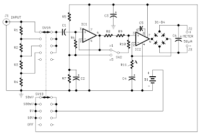
This electronic circuit is audio milivolt meter. It measures 10mV to 50Volt RMS in eight ranges.

Precision Audio Millivoltmeter Circuits Diagram

Precision Audio Millivoltmeter Circuits Diagram

 Notes:
  • Connect J2 and J3 to an Avo-meter set to 50µA range:
  • Switching SW2 the four input ranges will be multiplied by 5
  • Total fsd ranges are: 10mV, 50mV, 100mV, 500mV, 1V, 5V, 10V, 50V
  • Set R11 to read 1V in the 1V range, with a sine wave input of 1V @ 1KHz
  • Compare the reading with that of another known precision Millivoltmeter or with an oscilloscope.
  • The oscilloscope reading must be a sinewave of 2.828V peak to peak amplitude
  • Frequency response is flat in the 20Hz-20KHz range
  • If you have difficulties in finding resistor values for R1, R2, R3 & R4, you can use the following trick:
    R1 = 10M + 1M in parallel
    R2 = 1M + 100K in parallel
    R3 = 100K + 10K in parallel
    R4 = 1K2 + 6K8 in parallel
    All resistors 1/4W 1% tolerance 

Parts:

R1_____909K    1/2W 1% Metal Oxide Resistor
R2______90K9   1/2W 1% Metal Oxide Resistor
R3_______9K09  1/2W 1% Metal Oxide Resistor
R4_______1K01  1/2W 1% Metal Oxide Resistor
R5_____100K    1/4W Resistor
R6_______2M2   1/4W Resistor
R7______82K    1/4W Resistor
R8______12K    1/4W Resistor
R9_______1K2   1/4W Resistor
R10______3K3   1/4W Resistor
R11____200R    1/2W Trimmer Cermet
 
C1_____330nF   63V Polyester Capacitor
C2,C3__100µF   25V Electrolytic Capacitor
C4_____220µF   25V Electrolytic Capacitor
C5______33pF   63V Polystyrene Capacitor
C6_______2µ2   63V Electrolytic Capacitor
 
D1-D4___1N4148 75V 150mA Diodes
 
IC1_____CA3140 Op-amp
IC2_____CA3130 Op-amp
 
SW1_____2 poles 5 ways rotary switch
SW2_____SPDT switch
 
J1______RCA audio input socket
J2,J3___4mm. output sockets
 
B1______9V PP3 Battery
 
Clip for PP3 Battery

Readmore → Precision Audio Milli volt meter Circuits Diagram

Monday 21 November 2016

Motorcycle Alarm Circuit Diagram


This is a Motorcycle Alarm Circuit Diagram. Any number of normally open switches may be used. Fit the mercury switches so that they close when the steering is moved or when the bike is lifted off its side-stand or pushed forward off its center-stand. Use micro-switches to protect removable panels and the lids of panniers etc. While at least one switch remains closed, the siren will sound. 

 Motorcycle Alarm Circuit Diagram

Motorcycle Alarm Circuit Diagram


About tw1o minutes after the switches have been opened again, the alarm will reset. How long it takes to switch off depends on the characteristics of the actual components used. But, up to a point, you can adjust the time to suit your requirements by changing the value of C1.The circuit board and switches must be protected from the elements. Dampness or condensation will cause malfunction.Without its terminal blocks, the board is small. Ideally, you should try to find a siren with enough spare space inside to accommodate it. Fit a 1-amp in-line fuse close to the power source. 

This protects the wiring. Instead of using a key-switch you can use a hidden switch; or you could use the normally closed contacts of a small relay. Wire the relay coil so that it is energized while the ignition is on. Then every time you turn the ignition off, the alarm will set itself.When it`s not sounding, the circuit uses virtually no current. This should make it useful in other circumstances. For example, powered by dry batteries and with the relay and siren voltages to suit, it could be fitted inside a computer or any thing else that`s in danger of being picked up and carried away. The low standby current and automatic reset means that for this sort of application an external on/off switch may not be necessary.

Sourced by : Streampowers

Readmore → Motorcycle Alarm Circuit Diagram

Gretsch ControFuzz


Readmore → Gretsch ControFuzz

DC to DC Converter Circuit


Discription 
The circuit below is a DC to DC converter using a standard 12 VAC center tapped power transformer wired as a blocking oscillator. The circuit is not very efficient but will produce a high voltage usable for low power applications. The input battery voltage is raised by a factor of 10 across the transformer and further raised by a voltage tripler consisting of three capacitors and diodes connected to the high voltage side of the transformer. The circuit draws about 40 milliamps and should operate for about 200 hours on a couple of 'D' alkaline batteries. Higher voltages can be obtained by reducing the 4.7K bias resistor.
Circuit Diagram
 Source - http://www.bowdenshobbycircuits.info/page4.htm#triple.gif

Readmore → DC to DC Converter Circuit

Build a 25W Bridge Audio Amplifier with TDA2005


This is the 25W bridge audio amplifier built using single power IC TDA2005. Actually, the TDA2005 is a stereo power amplifier chip. It has two input channels and two output channel and delivers about 10W power output for each channel, since it connected in bridge mode then it will delivering up to 25W audio output. Take a note that the speaker terminals should not conected to the ground and mount the IC on the heatsink to prevent overheating.

 25W Bridge Audio Amplifier with TDA2005 Circuit Diagram

25W Bridge Audio Amplifier with TDA2005

Parts List:
R1 = 120K?
R2,5,6 = 1K?
R3,4 = 12?
R7,8= 1?
C1,5,7 = 220uF/25V
C2,10,11 = 100nF
C3,4 = 2.2uF/25V
C6,8 = 100uF/25V
C9 = 10uF/25V
IC1 = LM2005M / TDA2005

Readmore → Build a 25W Bridge Audio Amplifier with TDA2005

Understanding Processor Architecture RISC versus CISC


Popular processor designs can be broadly divided into two categories: Complex Instruction Set Computers (CISC) and Reduced Instruction Set Computers (RISC). The dominant processor in the PC market, Pentium, belongs to the CISC category. However, the recent trend is to use the RISC designs. Even Intel has moved from CISC to RISC design for their 64-bit processor.
RISC vs. CISC: What is the differences?


CISC systems use complex instructions. For example, adding two integers is considered a simple instruction. But, an instruction that copies an element from one array to another and automatically updates both array subscripts is considered a complex instruction. RISC systems use only simple instructions. Furthermore, RISC systems assume that the required operands are in the processor’s internal registers, not in the main memory. It turns out that characteristics like simple instructions and restrictions like register-based operands not only simplify the processor design but also result in a processor that provides improved application performance.

Several factors contributed to the popularity of CISC in the 1970s. In those days, memory was very expensive and small in capacity. Even in the mid-1970s, the price of a small 16 KB memory was about $500. So there was a need to minimize the amount of memory required to store a program. An implication of this requirement is that each processor instruction must do more, leading to complex instruction set designs. Complex instructions meant complex hardware, which was also expensive. This was a problem processor designers grappled with until Wilkes proposed microprogrammed control in the early 1950s.


Figure 1. The ISA-level architecture can be implemented either directly in hardware or through a microprogrammed control.

A microprogram is a small run-time interpreter that takes the complex instruction and generates a sequence of simple instructions that can be executed by the hardware. Thus the hardware need not be complex. Once it became possible to design such complex processors by using microprogrammed control, designers went crazy and tried to close the semantic gap between the instructions of the processor and high-level languages. This semantic gap refers to the fact that each instruction in a high-level language specifies a lot more work than an instruction in the machine language. Think of a while loop statement in a high-level language such as C, for example. If we have a processor instruction with the while loop semantics, we could just use one machine language instruction. This explains why most CISC designs use microprogrammed control, as shown in Figure 1.

RISC designs, on the other hand, eliminate the microprogram layer and use the hardware to directly execute instructions. Here is another reason why RISC processors can potentially give improved performance. One advantage of using microprogrammed control is that we can implement variations on the basic ISA architecture by simply modifying the microprogram; there is no need to change the underlying hardware. Thus it is possible to come up with cheaper versions as well as high-performance processors for the same family of processors.

References

  • Guide to RISC Processors for Programmers and Engineers by Sivarama P. Dandamudi, Springer (2005), ISBN 0-387-21017-2.

Readmore → Understanding Processor Architecture RISC versus CISC

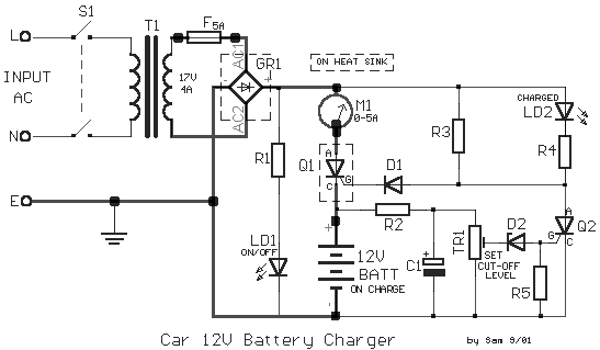
Car Battery Charger 12Volt Circuit Diagram


Car Battery Charger 12Volt Circuit DiagramCar Battery Charger 12Volt Circuit Diagram

The aloft circuit claimed accept adeptness to anticipate array blackmail that accomplish electrolyte absent due to evaporation. This ambit will annihilate the problems by ecology the battery’s action of allegation through its attendant ascendancy ambit by applying a aerial allegation accepted until the array is absolutely charged. Back charging is complete, it turns on the red LED (LD2) and deactivates the charging circuit.

This ambit is fatigued to allegation 12V batteries ONLY. Certain accent should be taken back base up this circuit. They are the access of the agent to the ambit board, and those bartering accepted to the array actuality charged. These access should be fabricated with cables accepting a ample cross-sectional breadth to anticipate voltage-drop and calefaction accession back accepted flows through them.


Readmore → Car Battery Charger 12Volt Circuit Diagram

Maximum Minimum Voltage Indicator


This circuit indicates which of three voltages in the range from about about -4V to about +4V - at A, B and C - is the highest by lighting one of three indicator LEDs. Alternatively, it can be wired to indicate the lowest of three voltages or to indicate both the highest and lowest voltages. Op amps IC1a, IC1b & IC1c are wired as comparators, while the three indicator LEDs and their series 1kO current limiting resistors are strung across the op amp outputs to implement the appropriate logic functions.


maximum-minimum-voltage-indicator circuit diagram Maximum Minimum Voltage Indicator Circuit Diagram
For example, LED A will light only when pin 8 of IC1c is low (ie, A greater B) and pin 7 of IC1b is high (ie, A greater C). Similarly, LED B will light only when pin 8 of IC1c is high (ie, B greater A) and pin 1 of IC1a is low (ie, B greater C). LED C works in similar fashion if the voltage at C is the highest. Note that if all the LEDs and their parallel 1N4148 diodes are reversed, the circuit will indicate the lowest of the three input voltages. And if each 1N4148 diode is replaced by a LED, the circuit will indicate both the highest and lowest inputs.

Author: Andrew Partridge - Copyright: Silicon Chip

Readmore → Maximum Minimum Voltage Indicator

Simple Fish Caller Circuit


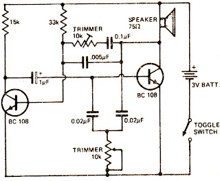
A lot of controversy exists among amateur fishermen as to the effectiveness of "fish-callers". Some swear by them, others just shake their heads. Here’s an inexpensive way of finding out. The two·transistor circuit drives the speaker. 

Varying the two potentiometers produces a wide variety of sounds. You may be lucky and hit on one that will bring in the big ones. An inexpensive waterproof housing is thick walled polythene bag with a few lead sinkers inside. An on-off toggle switch can be manipulated without opening the bag when switching power on and off. The bag opening is sealed with good quality electrical tape to make system waterproof. Tape seal should be renewed after each use.


Circuit Diagram :


Simple Fish Caller Circuit

Readmore → Simple Fish Caller Circuit

Sunday 20 November 2016

TRANSISTOR TESTER CIRCUIT USING NE555


Readmore → TRANSISTOR TESTER CIRCUIT USING NE555

3 Watt stereo amplifier circuit


3 Watt stereo amplifier circuit using MAX 7910 IC. The MAX9710 a stereo audio power amplifier IC capable of delivering 3Watts of out put to 4 Ohm loads. MAX9710 can be operated from a single 4.5V to 5.5V power supply , makes it ideal for hand held applications.The IC for 3 Watt stereo amplifier circuit also features thermal overload protection.


Circuit Schematics 3 Watt  Stereo Amplifier MAX 7910 
3 Watt stereo amplifier circuit
3 Watt stereo amplifier circuit 

This 3 Watt stereo amplifier circuit  is suitable for small power audio devices such as radio sets and portable CD players. 5 V DC power supply is used for powering the 3 Watt stereo amplifier circuit. 6V battery with an IN 4007 diode series to the positive terminal of it can also be used instead of 5 V DC supply. The 3 Watt stereo amplifier circuit will get a supply voltage approximately 5 V after 0.7 V voltage drop across diode.


Readmore → 3 Watt stereo amplifier circuit

White line Flower Circuit Diagram


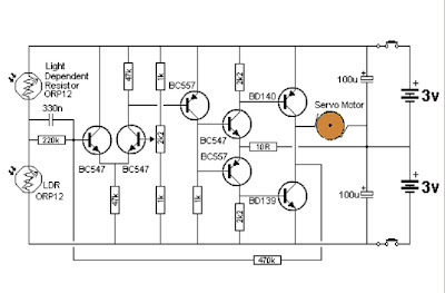
This circuit will be used for a toy automotive to follow a white line. The motor is either a 3v sort with gearing to steer the automotive or a rotary actuator or a servo motor.When equal lightweight is detected by the photo resistors the voltage on the base of the primary transistor are mid rail and the circuit is adjusted via the 2k2 pot that the motor doesn't receive any voltage. When one in all the LDR's receives a lot of (or less) lightweight, the motor is activated. and also the same thing happens when the other LDR receives less or more light.


White line Flower Circuit Diagram

White line Flower Circuit Diagram


Readmore → White line Flower Circuit Diagram

Build an AC Mains Short Circuit Protector Circuit Diagram


The simple short circuit and overload protector design presented here can be used for protecting valuable mains operated gadgets like amplifiers, TV sets, DVD players or any other similar appliance.Normally all sophisticated gadgets today incorporate an in built short circuit protector arrangement, yet still adding a more comprehensive external protection device could only benefit the connected system.

Moreover, for gadgets such as amplifiers which are home built this protection device could prove to be very effective and useful. Also for an hobbyist who prefers building electronic gadgets at home could be greatly benefited with the present idea.

The presented short circuit protector design works on a very basic principle and costs not more than a couple of dollars.

Let's learn the functioning details of the proposed circuit.

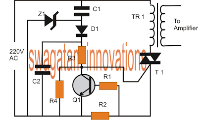
On applying power, the high current from the 220V input is dropped sufficiently by C1, rectified by D1 and filtered by C2 to feed the gate of the triac T1.

The triac conducts and switches ON the connected transformer primary thus switching ON the load which in this case is a power amplifier.

The transistor Q1 along with R1, R2 forms a current sensor stage.

R2 specifically is chosen such that it develops adequate voltage across itself at the specified dangerous high current threshold.

As usual the formula for determining R2 = 0.6/current(A)

As soon as the triggering voltage accumulates across R2, Q1 activates and sinks the gate voltage of the triac to ground making it switch off.

The regulation continues as long as the short or overload condition is not removed.

The above short circuit regulation ensures that the current level above the specified dangerous level is restricted safeguarding the precious devices associated with the connected amplifier.

If a latching feature is required for the above design, the emitter Q1 can be configured with an SCR and the SCR can be used for latching and switching off the triac.


AC Mains Short-Circuit Protector Circuit Diagram

AC Mains Short-Circuit Protector Circuit Diagram


Parts List


R1 = 100 ohms
R2 = see text
R3 = 1k
R4 = 10k
C1 = 0.33/400V
C2 = 1uf/250V
Q1 = BC547
Z1 = 12V/1 watt zener diode
T1 = BT136 or as per current rating
TR1 = As per load requirement specs.


Source By Swagatam

Readmore → Build an AC Mains Short Circuit Protector Circuit Diagram

Saturday 19 November 2016

Wave antenna 5 8 pro VKV FM


Wave antenna 5/8 consists of a vertical radiator which is fed at the base of the antenna. A suitable device of some sort should be added between the antenna and feedline if you want to eat with coax. Adding a coil in series with the antenna on the base is one of these methods are suitable. 


So why would anyone use an antenna 5/8 wave if they have to go through all that extra work? After all, a ground plane antenna provides a good match. There are several answers. The first is GAIN. The computer shows that the antenna (mounted 1 foot above the ground) has a margin of about 1.5 dBd higher than a dipole (also installed 1 foot above the ground.)The second reason you might want to use the wave 5/8 vertical is to get a lower angle of radiation. Peak radiation angle A half-wave antenna is 20 degrees. You will find that the angle 5/8 wave antenna radiation is only 16 degrees so it is better dx antenna. 

 You may have noticed a pattern developing here. A quarter-wave ground plane antenna has a radiation pattern that produces the maximum gain at about 25 degrees and half-wave antenna drops to 20-degree angle, and wave antenna 5/8 further drops to 16 degrees angle. So why not just keep extending the antenna to one full wave? Well it would be nice if it worked, but unfortunately the wave patterns begin to create a very high angle of radiation waves exceed 5/8. So we've reached the maximum gain at this point and extend the antenna further reduce profits only where we want it (low angle). 

Of course if you are interested in a very short jump, extend the antenna will produce a nice profit on the dipole.All the length of the antenna depends on various factors. Some of these factors are: height above ground, the diameter of the wire, nearby structures, the effects of other antennas in the area and even the conductivity of the soil.This page allows you to calculate the wavelength for the antenna 5/8. It uses the standard formula, 585 / f (178.308 / f for metric) MHz to calculate the length of the element. If you have experimented with 5/8 wave antenna before and know a better formula for your QTH, feel free to change the formula accordingly. This formula is for the antenna wire. 

Of course if you build your antenna out of the tube, total length of the antenna will be shorter, for example I have found that 21.5 feet seems to provide maximum benefit to the frequency of 28.5 MHz when using a 1 "tube, and 22.5. Foot seems be the best long-wire at the same frequency. Since the formula to calculate the antenna to be about 2 feet shorter, be sure to experiment and maybe add a little for your final term.

Readmore → Wave antenna 5 8 pro VKV FM