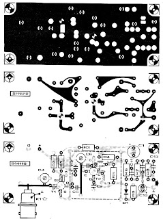
The receiver is intended primarily for use with the remote control UHF transmitter described in the preceding article. It is a super-regenerative type with an active RF amplifier, T1. The antenna signal is applied to the input inductor via a BNC socket, K1. The input circuit is tuned by trimmer C4. The amplified RF signal is applied to the input of the super-regenerative stage based on transistor T2. Although the oscillator is, strictly speaking, not tuned, it will lock on to the amplified RF signal applied via coupling capacitor C7. The low-frequency modulation component is extracted from the oscillator signal with the aid of low-pass filter, R6-R7-C12-R8-C13. The signal level at the demodulator output is 50 to 800 mVpp, so that further amplification is required·before the signal can be applied to a digital input. The inductors in the RF amplifier input and output are made from 1 mm dia. silver-plated wire. The length of the pieces of wire is indicated by the component overlay. The wires run at a height of about 3 mm above the board surface. Note that the stator terminal of C4 is bent upwards and soldered direct to the input inductor. The same goes for junction C6-C7, which is soldered ‘in the air‘, directly op to the hot end of the inductor wire. Inductor L1 consists of 12 turns of 0.6-mm dia. enamelled copper wire. Its internal diameter is 3 mm. Each of chokes g and L3 consists of 4 turns of 0.2-mm dia enamelled copper wire through a 3 mm long ferrite bead. Capacitor C8 is a surface-mount technology (SMT) type which is fitted at the solder side of the board, as are the BFG65 and the BFQSO. The type indica- tion printed on the transistors is legible from the component side of the board. As indicated by the dashed lines on the component overlay, the super-regenerative section of the circuit must be screened from the rest. To do this, it is best to solder a 20 mm high tin plate box on to the PCB as indicated.
For the transmitter circuit : UHF FM Remote Control Transmitter Circuit
When the SDA (Serial DAta) lines on both the left and right lines are 1, the circuit is quiescent and optoisolators IC1 and IC2 are not actuated. When the SDA line at the left becomes 0, current flows through the LED in IC1 via R2. The SDA line at the right is then pulled low via D2 and IC1. Optoisolator IC2 does not transfer this 0 to the left, because the polarity of the LED in IC2 is the wrong way around for this level. This arrangement prevents the circuit holding itself in the 0 state for ever. As is seen, the circuit is symmetrical. So, when the SDA line at the right is 0, this is transferred to the left. The lower part of the diagram, intended for the SCL (Serial CLock) line, is identical to the upper part.
Circuit diagram :
Electrical Isolation For I2C Bus Circuit Diagram
Resistors R1, R4, R5, and R8, are the usual 3.3 kΩ pull-up resistors that are obligatory in each I2C line. If these resistors are already present elsewhere in the system, they may be omitted here. The current drawn by the circuit is slightly larger than usual since the pull-up resistors are shunted by the LEDs in the optoisolators and their series resistors. Nevertheless, it remains within the norms laid down in the I2C specification.
The Basic Alarm Circuit has an automatic Exit/Entry Zone - an Instant Alarm Zone that will accept both normally-closed and normally-open triggering devices - and an "Always On" 24-hour Personal Attack/Tamper Zone. By using the Expansion Modules - you can add as many extra alarm zones as you require.
Schematic Diagram
The Alarm is armed and disarmed by SW1. Before you move the switch to the "set" position - all the green LEDs should be lighting. You then have up to about a minute to leave the building. As you do so - the Buzzer will sound. It should stop sounding when you close the door behind you. This indicates that the Exit/Entry loop has been successfully restored within the time allowed.
When you re-enter the building - you have up to about a minute to move SW1 to the "off" position. If SW1 is not switched off in time - the relay will energize - and the main bell will ring. It will continue ringing for up to about 40 minutes. But it can be turned off at any time by SW1.
The "Instant" zone has no Entry Delay. The moment one of its normally-open switches is closed - the main bell will ring. Similarly - the moment one of its normally-closed switches is opened - the main bell will ring. If you don't want to use normally-open switches - leave out R8, C8 and Q2 - and fit a link between Led 3 and C7.
The 24 Hour Personal Attack and Tamper protection is provided by the SCR/Thyristor. If one of the switches in the normally-closed loop is opened - current through R11 will trigger the SCR - and the main bell will ring. In this case the bell has no time limit. To reset the PA/Tamper zone - first restore the normally-closed loop - then press SW2 momentarily. This will interrupt the current and reset the SCR.
Two-Zone Expansion Module
The basic circuit will be satisfactory in many situations. However, if you have a large building to protect - it's much easier to find a fault - when the system is divided into zones - and the control panel can "remember" which zone has caused the activation.
The expansion modules are designed to do this. Although they will work with the existing instant zone - they are intended to replace it. When a zone is triggered - its red LED will light and remain lit - to indicate that the zone has been activated.
The idea is that - once you've noted the zone in question - you then press the reset button and turn off the LED. The reset button simply turns off the LED. It doesn't reset the zone. The zone resets automatically when the trigger circuit is restored. If you're using more than one expansion module - they can all share a single reset button.
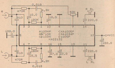
In this series I use IC tda2822M as the main amplifier, but if you want to use in addition to IC TDA2822M you can use ic I mentioned this is KA2209, NJM2073, U2822B, U2823B. Output is issued no more than 4W, which had low output. Supply voltage from 3 volts to 16 volts.
Below its schematics of TDA2822 stereo audio power amplifier
Energy conservation is the prime purpose of the design MSTDO. One particular application of the MSTDO is pressing of stairway lamps in a multi-storey building. When one desires to reach a certain floor level using the stairway, see figure below (A)
, he will return on the stairway lamps (L1,L2,L3…Ln) by pressing any one of the stairways push button switches (S1,S2,S3…N3). A sufficient time is allowed for him to reach his desire floor level destination. He need not turn off or push any switches to turn off the stairway lamp. The stairway lamp will be automatically turn off.
(A) Push button switches and lamps installed in the stairway of a multi-storey building.
Control Operation
Referring to figure below (B), the neon lamps (N1,N2,N3…Nn) together with push button switches (S1,S2,S3…Sn) respectively installed in each stairway level are initially lighted on. The neon lamps are guide someone to reach on the stairway switches especially at night time. The stairway lamp (L1,L2,L3…Ln). Contact C (11-12)n will open to de-energize (light-off) condition.
Pressing any one of the stairway switches (S1,S2,S3…Sn) will energize the timer TR ( 2-7) and contactor C. Normally open instantaneous contact TR (1-3) will close to maintain the timer (2-7) and contactor C continuously energized even the press push button is stop. Contact C (1-2,3-4,5-6) will close to energized the stairway lamps L1,L2,L3…Ln) contact C (11-12) will open to de-energized the neon lamps (N1,N2,N3…Nn).
(B) Schematic diagram of the control circuit for “Multi Switching System with Automatic Time Delay Off”.
After several minute, the time sufficiently set to allow a person travel from the lowest to the highest floor level, the normally closed time delay contact TR (8-5) will open to de-energized the timer TR (2-7) and contactor C. Contacts C (1-2,3-4.5-6) will open to de-energized ,the stairway lamps (L1,L2,L3..Ln). Contact C ( 11-12) will close to its initial condition to energized the neon lamps (N1,N2,N3..Nn). Delay contact TR (8-5) will close and instantaneous contact TR (1-3) will open.If it is desire again to energize the stairway lamps (L1,L2,L3…Ln) one has to press again any one of the stairway way push button switches (S1,S2,S3…Sn).
A dc level is produced that corresponds to the ac input rms value (if sine wave), -i set the gain of IC2 to 1.11. This factor is the average-to-rms conversion factor. IC1 and IC2 act as a full-wave rectifier circuit, with Dl and D2.
Replace your filters regularly - Close the windows
Replace your filters regularly.
Most heating and cooling equipment require clean filters, in order for them to run clean. The filters can also help them in becoming more energy efficient. With that, replacing your filters regularly can help you save a lot in terms of energy consumption. Ask your technician about it, so that you would know when is the best time to do so.
Dirty coils make your appliances consume more electricity. Refrigerator coils can get dirty over a certain period of time. In most cases, they can accumulate a lot of dirt within the six month period; and, when that happens, the dirty coil would make your refrigerator work harder in order to achieve its desired temperature. Thus, it is best if you practice cleaning and vacuuming your refrigerator coils every six months or so, so that you won’t have to endure higher electricity bills.
Close the windows.
Whether you need to achieve lower or higher temperature inside your house, it is best if you close your windows. This is because, open windows would make your cooling or heating equipment require more energy to serve you better. When you close the windows, your equipment would not work too hard, which means it can help you save energy.
This circuit uses the popular and easy to find LM3914 IC. This IC is very simple to drive, needs no voltage regulators (it has a built in voltage regulator) and can be powered from almost every source.
Circuit diagram :
Simple but reliable car battery tester Circuit Diagram
When the test button is pressed, the Car battery voltage is feed into a high impedance voltage divider. His purpose is to divide 12V to 1,25V (or lower values to lower values). This solution is better than letting the internal voltage regulator set the 12V sample voltage to be feed into the internal voltage divider simply because it cannot regulate 12V when the voltage drops lower (linear regulators only step down).
Simply wiring with no adjust, the regulator provides stable 1,25V which is fed into the precision internal resistor cascade to generate sample voltages for the internal comparators. Anyway the default setting let you to measure voltages between 8 and 12V but you can measure even from 0V to 12V setting the offset trimmer to 0 (but i think that under 9 volt your car would not start). There is a smoothing capacitor (4700uF 16V) it is used to adsorb EMF noise produced from the ignition coil if you are measuring the battery during the engine working. Diesel engines would not need it, but I'm not sure. If you like more a point graph rather than a bar graph simply disconnect pin 9 on the IC (MODE) from power.
For the first comparator the voltage is : 0,833 V corresponding to 8 V * * * * * voltage is : 0,875 V corresponding to 8,4 V for the last comparator the voltage is : 1,25 V corresponding to 12 V Have fun, learn and don't let you car battery discharge... ;-)
The circuit above shows a 4-transistor utility amplifier suitable for a variety of projects including receivers, intercoms, microphones, telephone pick-up coils, and general audio monitoring. The amplifier has a power isolation circuit and bandwidth limiting to reduce oscillations and "motorboating". The values are not particularly critical and modest deviations from the indicated values will not significantly degrade the performance.
Three cell battery packs giving about 4.5 volts are recommended for most transformerless audio amplifiers driving small 8 ohm speakers. The battery life will be considerably longer than a 9 volt rectangular battery and the cell resistance will remain lower over the life of the battery resulting in less distortion and stability problems.
4 Transistor Amplifier for Small Speakers Circuit
The amplifier may be modified to work with a 9 volt battery if desired by moving the output transistors' bias point. Lowering the 33k resistor connected from the second transistor's base to ground to about 10k will move the voltage on the output electrolytic capacitor to about 1/2 the supply voltage.
This bias change gives more signal swing before clipping occurs and this change is not necessary if the volume is adequate. As before, the two 4.7 ohm resistors may be replaced with a single 10 ohm resistor in series with either emitter.
This Pre-regulated High Voltage Power Supply Circuit Diagram triacs selects the tap on main transformer Tl, which provides the proper, pre-regulated voltage to the secondary regulator. T2 and its associated components comprise the secondary regulator. The ADC 0804, IC1, digitizes a voltage-feedback signal from the secondary regulator`s output.
Pre-regulated High Voltage Power Supply Circuit Diagram:
The MC1415 De-multiplexer, IC2, decodes the digitizer`s output. IC2, in turn, drives Tl`s opto-isolated triacs via the 74LS240 driver chip, IC3, and associated opto-isolators. Transformer T3 samples the circuit`s current output. The auxiliary, 12 V winding on Tl ensures noload starting. The combination of op amp IC5 and the inverting transistor, Ql, square this current signal.
The output of Ql is the CLK signal, which triggers one-half of the one shot, IC4A, to begin the circuit`s AID conversion. The one shots` periods are set to time out within 1l2 cycle of the ac input. Upon completion of its AID conversion, ICl`s INTR output triggers the other half of the one shot, IC4B, which enables the converter`s data outputs. The rising edge of the CLK signal resets the one shot and latches the new conversion value into IC2. The latch, associated driver, and optoisolator trigger a selected triac according to the latest value of the voltage-feedback signal, V, . Keep enjoying don't forget click on share button .
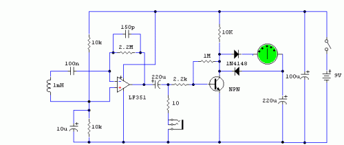
This lovely circuit is a real gem! Easy to assemble and more sensitive than many commercial devices available. It's based around an LF351 low-noise operational amplifier and a 1mF choke acting as the sensor. Unlike most other simple EMF detectors, this one has a meter output for accurate reading, but alternatively, you can also roughly estimate the frequency of the field by plugging in headphones. It can detect any field from 50Hz to 100kHz, making it highly versatile and a worthwhile addition to any hobbyist's workbench.
Problems: I just couldn't find any. Possible uses:
Find out how far electromagnetic fields extend in your room, house, office...
Are you a ghost hunter? Then this is the circuit that you've been waiting for! Since it has been observed that appearance of a ghost tends to disturb the EMF, you can now detect any such changes with this little detector.
Author: Andy Collins' Circuit Exchange Source - http://www.zen22142.zen.co.uk/
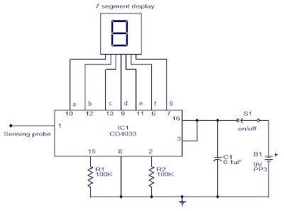
This circuit can be used to test whether mains voltage is present or not without having electric contact with mains line. The CMOS IC CD4033 is the heart of this circuit. The CD4033 consists of a 5 stage decade Johnson counter and an output decoder for converting the Johnson code to a 7 segment decoded output for driving 7 segment LED display. A 10cm long insulated copper wire connected to the clock pin (pin1) of the IC serves as the sensor.
Wireless Mains Voltage Tester Circuit diagram:
The sensor wire has to be placed in the vicinity of the mains wire to be tested. When there is no voltage in the mains line, no voltage will be induced in the sensor wire and the display will show a random digit. When there is voltage in the mains line, a small voltage will be induced in the sensor wire due to electromagnetic induction and this voltage is sufficient enough to clock the CMOS IC CD4033. Now the display will count from zero to nine and repeat.
An AC-DC voltage converter with electrically isolated with onput and output circuits and converters with a transformer with at least one primary coil and a capacitor resonance said coil to at least one primary school.
A switching transistor whose collector-emitter path is connected in series at least a coil and the primary school to the transistor switching system for the storage in the database of the surface sensors.
switching power transistor provides the foundation for the transistor switching system, and by other means in order to increase the voltage transmitter Collector of the transistor switching and deliver a response to such an increase and at least in the period immediately after the increase.
one while driving for the transistor circuit, the additional base current is very progressive with a predetermined, so that the storage of the relatively constant switching transistor in the beach for the operation of the converter.
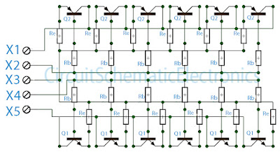
The above circuit is a circuit of booster amplifiers or amplifier end of a power amplifier circuit, Circuit over in the most important influence whether or not , and many more are affected in this final series. Because the booster circuit is the amplifier end of the work was too heavy components causing the rapid component of the heat. If we are wrong then consequences will install components that can cause fatal damaged direct component , such us the installation of pin emiter, collector , and base everything must be correct. In the circuit above can strengthen booster amplifier with maximum work and everything is evenly split, what is it evenly split ? evenly split the point here is that all components can work with the same voltage and the heat evenly , this is because at each respetive base transistor were given the same constrains and same wattage resistor. And to maintain if the power output is too large then the resistor on Re will hamper so that the transistor is not easily broken.
Part List : Rb=10R/1W Re=0,5-1R/5W Q1=Transistor power NPN such us 2N3055 , TIP3055,TIP120,TIP142,2SC2922 , etc. Q2=Transistor Power PNP such us MJ2955 ,TIP2955,TIP125,TIP147,2SA1216, etc. X1=Voltage connector (-) X2=PNP Base connector X3=Speaker connecor but also must be connected from the buffer X4=NPN base connector X5=Voltage connector (+)
This is the New Simple Lie detector Circuit Diagram. The two probes shown are held in the hands and the skin resistance applies bias to the transistor.
New Simple Lie detector Circuit Diagram
The 5 k ohm pot is set for zero deflection on the meter. When the ' 'subject'' is embarrassed or lies, sweating on the hands takes place, increasing the bias to the transistor and upsetting the bridge balance.
Do you also struggle reading your own and others huge ladder diagrams? The truth is, that even though ladder diagram (LD) is an easy programming language for beginners, it can be very hard to read and understand. That’s why Structured Text is a better PLC programming language, and you can learn it in this tutorial.
It can be almost impossible to find head and tail in a larger PLC program written in ladder logic. So, what might seem easy to learn (especially for technicians and electricians) is not always the best thing to program in. Your ladder diagram will be hard to understand for others than yourself. How can I be sure about that? Try it yourself. Take a look at one of these ladder logic examples, and see how long it takes to understand it. See my point? Luckily for us there’s a better PLC programming language available. It’s called Structured Text.
What is Structured Text Programming?
Structured Text is PLC programming language defined by PLCOpen in IEC 61131-3. The programming language is text-based, compared to the graphics-based ladder diagram. At first, it may seem better to use a graphical programming language for PLC programming. But in my opinion, that is only true for smaller PLC programs. By using a text-based PLC programming language, your program will take up much smaller space, and the flow/logic will be easier to read and understand. Another advantage is that you can combine the different programming languages. You can even have function blocks containing functions written in Structured Text. The fact that this is a standardized programming language also gives us the option to program different PLC brands with Structured Text. Probably the most common PLC (in Europe at least) is the Siemens S7 PLC’s. They can be programmed with Structured Text and you can start already now with the Siemens S7-1200 Starter Kit, which is also a great kit to get you introduced to the Siemens PLC environment.
High-level Programming Languages
If you are already familiar with high-level programming languages like PHP, Python and C, Structured Text will seem familiar to you. The syntax of Structured Text is developed to look like the syntax of a high-level programming language with loops, variables, conditions and operators. But on the other hand, if you have never seen a high-level programming language, Structured Text can be a great introduction to those languages and the syntax used. Before you read this tutorial I recommend that you take a brief look at this PLC program written in Structured Text. Try to see if you can understand the function of this program. Does Structured Text look familiar to you?
PROGRAM stexample
 VAR
 x : BOOL;
 END_VAR
 x := TRUE;
 REPEAT
 x := FALSE;
 UNTIL x := FALSE;
 END_REPEAT;
END_PROGRAM;
The Flow of Structured Text
The first thing you should learn is the structure or the syntax of Structured Text. When you understand the structure, you will understand how the flow of your program works. Starting with the example above, you can see that the whole program begins with PROGRAM and ends with END_PROGRAM. Everything in between is your PLC program. These two words are the delimiting keywords for program declarations. More on keywords later. Don’t be confused about the END_PROGRAM, because your program won’t end completely here. When the PLC reaches the END_PROGRAM the PLC scan cycle will start over again, and your program will repeat itself.
Structured Text Program Flow.
This is just like ladder logic or any other PLC programming language – it will run over and over again. And if you are used to programming microcontrollers, the PROGRAM/END_PROGRAM will be similar to the infinite loop in C. NOTE: One thing to add here is that, when you are programming in Structured Text, you will often not use the PROGRAM/END_PROGRAM construct. It will already be done by the PLC programming software, and the code you have to write, is what you want inside that construct. The flow control of PLC programs written in Structured Text is the same as in ladder logic: execute one line at a time.
Starting with the Syntax of Structured Text
The syntax of a programming language is the definition of how it is written. To be more precise, what symbols is used to give the language its form and meaning. As you can see in the example, Structured Text is full of colons, semicolons and other symbols. All these symbols has a meaning and is used to represent something. Some of them are operators, some are functions, statements or variables. All the details of the syntax will be explained as you move through this tutorial. But there are some general rules for the syntax of Structured Text you should know about. You don’t have to memorize all the syntax rules for now, as you will when you get your hands into the programming:
All statements are divided by semicolons Structured Text consists of statements and semicolons to separate them.
The language is not case-sensitive Even though it is good practice to use upper- and lowercase for readability, it’s not necessary.
Spaces have no function But they should be used for readability.
What’s really important to understand here is that, when you write a PLC program in Structured Text, your computer will translate that to a language the PLC can understand. When you upload the Structured Text PLC program to your PLC, the programming software you use will compile your program. This means that it will translate the code to a sort of machine code which can be executed by the PLC. The compiler uses the syntax of the programming language to understand your program. For example: Each time the compiler sees a semicolon, it will know that the end of the current statement is reached. The compiler will read everything until it reaches a semicolon, and then execute that statement.
Comment Syntax
In textual programming languages you have the ability to write text that doesn’t get executed. This feature is used to make comments in your code. Comments are good, and as a beginner you should always comment your code. It makes it easier to understand your code later. In Structured Text you can make either one line comments or multiple line comments. Single line comment:
// comment
Comment after end of ST line:
<expression>; /* comment */
or
<statement>; (* comment *)
Multiple line comment:
/* start comment
...
end comment */
or
(* start comment
...
end comment *)
Should You Comment Every Detail?
As you gradually get better and better, you should make fewer and fewer comments about the functionality. The reason for this is The Tao of Programming, which is a book about programming inspired by the old Chinese Tao Te Ching. Or actually the principle behind the book is the reason. Take this little story in chapter 2.4:
A novice asked the Master: “Here is a programmer that never designs, documents or tests his programs. Yet all who know him consider him one of the best programmers in the world. Why is this?” The Master replied: “That programmer has mastered the Tao. He has gone beyond the need for design; he does not become angry when the system crashes, but accepts the universe without concern. He has gone beyond the need for documentation; he no longer cares if anyone else sees his code. He has gone beyond the need for testing; each of his programs are perfect within themselves, serene and elegant, their purpose self-evident. Truly, he has entered the mystery of Tao.”
Although this might be put on the edge, you should always write your code so it is as easy as possible to understand. Even without comments. You start doing this by simply making the code easy to read with spaces. But for now, you should not worry about comments. Make as many as you want while you are still a beginner.
Making Statements with Structured Text
So, Structured Text consists of statements. But what is statements? You probably know statements as something coming from humans. You can make a statement, a president or even a company can make a statement. And in PLC programming, statements are almost the same.
A statement is you telling the PLC what to do.
Let’s take the first statement as an example:
X : BOOL;
The compiler will read this as one statement, because when it reaches the semicolon, it knows that this is the end of that statement. Remember, statements are separated by semicolons. That’s the main syntax rule of this language. In this statement you are telling the PLC to create a variable called X and that variable should be a BOOL type.
Using Variables in Structured Text
Before we dig deeper into the statement, let me get back to the keywords i mentioned before. As you can see, the variable X is defined in between two other keywords – VAR and END_VAR. Both the PROGRAM/END_PROGRAM and VAR/END_VAR are constructs, meaning that they delimit a certain area in your program for something specific. The PROGRAM construct is where all your PLC program is, and the VAR construct is where you define variables. All the four are called keywords, because they are reserved words. You can’t use those words for anything else when you are programming in Structured Text. The name of your program cannot be PROGRAM or even program (STL is not case sensitive), because that word can only be used to make a construct to delimit your PLC program. Back to variables… If you know other programming languages, chances are that you know about variables already. But if you don’t, here’s an introduction to variables you probably will like:
A variable is a place where you can store data. Depending on what type of data you want to store, there are several data types available. The different kinds of data are called data types. For example, if you have a variable where you want to store either TRUE or FALSE, you can declare it as a BOOL type. The BOOL type is a boolean data type which means that it can contain a boolean value (TRUE or FALSE). Now, that was two thing about variables. They have a certain data type, and they contain a value of that data type. But there’s one more thing you can control in your variables. The name of the variable. To make it easy for you to use your variables throughout your PLC program, they all have names. When you define a variable in the VAR construct, you start by giving the varible its name:
X : BOOL;
This statement will create a variable called X, with a BOOL data type. Be aware, that when you are programming with some PLC software like Siemens STEP 7 or Rockwell you won’t use the VAR/END_VAR til declare variables. Instead variables are often called tags or symbols, and even though you are programming in Structured Text, you declare them visually (like in the image below) or in a function block.
Variables, Tags or Symbols?
One last thing to add here is that variables are often called tags in PLC programming. In the PLC programming software Studio 5000 Logix Designer for Allen Bradley PLC’s, variables are called tags. But if you are programming in older versions of SIMATIC STEP 7 Programming Software for Siemens PLC’s, variables are called symbols. In the newer versions of STEP 7 (from TIA Portal version 11) variables are called tags.
SIMATIC STEP 7 TIA Portal Variables called PLC tags.
But no matter what variables are called, they always have the same function. And with IEC 61131-3 Programming software like STEP 7, Codesys or Studio 5000, the standard data types will always be available.
Data Types in Structured Text
Depending on what PLC brand you are using, you will have some different data types available. In a Siemens PLC you have data types in STEP 7 available that are similar to the standard ones in IEC 61131-3. But you will also have other data types only used in SIEMENS PLC’s like the S5TIME. All the standard data types are defined by the PLCOpen Organization and they are part of the PLC programming languages. Every PLC programming software with Structured Text has these data types included. In the IEC standard the data types are divided into two categories: Elementary data types and derived data types. Elementary data types
Integers
Floating points
Time
Strings
Bit strings
Under each elementary data types there are several IEC data types available. These are the data types defined in IEC 61131-3: Integers:
The derived data types are your own custom data types. All the derived data types are built by making a construction of the keywords TYPE and END_TYPE. In between the keywords is the kind of derived data type you want to declare. All these different data types might seem a little overwhelming for now. Especially if you haven’t used a textual programming language before. But there’s no need to worry. For now, you only have to remember a few of them to get started programming with Structured Text. As you get better and your programs more complicated, you will gradually learn about more data types as you use them. What’s important here is that you don’t move ahead too fast. You want to get the basics right. As you can see the different data types can hold different data formats and thereby different values. But how do you put the values in the variables? And how do you use the variables? With statements and operators.
Operators and Expressions in STL
The next thing you should know about is operators. Operators are used to manipulate data and is a part of almost any programming language. This leads us to the second thing you should know about – expressions. Just like operators, expressions are a crucial part of programming languages. An expression is a construct that, when evaluated, yields a value. This means that when the compiler compiles an expression, it will evaluate the expression and replace the statement with the result. Take this example with the two variables A and B. A contains the value 10 and B contains 8.
A+B
The result of this expression is 18. So instead of A+B, the compiler will put in the value 18. An expression are composed of operators and operands. So what are operators and operands? Since, you just saw an example of an expression, you just saw both an operator and two operands. A and B are both operands and the + is an operator.
Programming language expressions with operands and operators.
Remember that operators are used to manipulate data. That is exactly what the + is doing. It is taking the value of the variable A and adding it to the value in B. The + is also called the addition operator because the operation is addition.
Operators
There are several operators available in Structured Text. Again, IEC 61131-3 describes all the standard operators in the Structured Text language:
Operation
Symbol
Precedence
Parenthesization
(expression)
Highest
Function Evaluation
MAX(A,B)
Negation Complement
– NOT
Exponentiation
**
Multiply Divide Modulo
* / MOD
Add Subtract
+ –
Comparison
<, >, <=, >=
Equality Inequality
= <>
Boolean AND Boolean AND
& AND
Boolean Exclusive OR
XOR
Boolean OR
OR
Lowest
All the operators in the table above are sorted after precedence. This is also called order of operations, and you may know about if from mathematics. The order of operations is the order in which the operations are executed or calculated. Just take a look at this expression:
A + B * MAX(C, D)
How will this expression be evaluated by the compiler? As you can see in the table of operators the operator with the highest precedence is parenthesis. This means that the first thing, that will be evaluated, is everything in parenthesizes – in this example: (C, D). But since MAX(C, D) is actually a function, we can jump one row down in the table to function evaluation. So, in the above expression, the first thing that will be evaluated is the function: MAX(C, D). The function will yield (replace the function) with the answer. Which in this case is the highest of the two variables C and D. Let’s image C is the result. The expression will now look like this:
A + B * C
Now, you can go down through the table, until you reach a row with the next operator used in this expression. There are two operations left: multiply and addition. But since multiply has a higher precedence, that will be the first to be evaluated. B * C comes first and then the result is added to A. Every time an expression is evaluated, the evaluation follows the order of precedence as in the table above.
4 Types of Operators, 4 Types of Expressions
The operators used for expressions in Structured Text can be divided into four groups. Each group of operators will have its specific function and will yield a specific data type.
Arithmetic Operators
Relational Operators
Logical Operators
Bitwise Operators
Arithmetic Operators
All the arithmetic operators are often just called mathematical operators because they represent math. The result will always be the mathematical result of the expression.
+ (add)
– (subtract/negate)
* (multiply)
** (exponent)
/ (divide)
MOD (modulo divide)
Example:
15 MOD 4
Result: 3
Relational Operators
To compare or find a relation between two values you can use one of the relational operators. They are used for comparison and the result will be a boolean value (BOOL type), either TRUE or FALSE.
= (equal)
< (less than)
<= (less than or equal)
> (greater than)
>= (greater than or equal)
<> (not equal)
Example:
TEMPERATURE := 93.9;
TEMPERATURE >= 100.0
Result: FALSE
Logical Operators
If you want to compare boolean values (BOOL) and make some logic out of it, you have to use logical operators. These operators also yields a boolean value of TRUE or FALSE as a result of the expression.
& or AND
OR
XOR
NOT
Example:
LIMIT_SWITCH1 := TRUE;
LIMIT_SWITCH2 := FALSE;
LIMIT_SWITCH1 OR LIMIT_SWITCH2
Result: TRUE
Bitwise Operators
The last group of operators are called bitwise operators because the operations are performed bitwise. It simply means that a logic operation is performed for each bit of two numbers. The result is a new number – the total result of the bitwise operations.
& or AND
OR
XOR
NOT
Example:
15 AND 8
Result: 15 Since this operation is bitwise the calculation will be per bit. So to understand what’s going on here, you have to convert the numbers to binary values: 15 = 1111 8 = 1000 Now each bit in the number 1111 (15) can be used in a logical operation with the other number 1000 (8):
1111 AND 1000
Bit number
1111 (15)
1000 (8)
Result
0
1
1
1
1
1
0
0
2
1
0
0
3
1
0
0
Operators and Statements
So, in the previous section you learned that expressions evaluate. Meaning that all expressions will yield the result and the compiler will replace the expression with the result. But what if you want the PLC (compiler) not to evaluate something, but to DO something? Statements are the answer. As I mentioned previously in this article, statements are you telling the PLC what to do. It’s the instruction you give the PLC to take action. If you make an expression that yields a result, that won’t do much. Expressions are all the calculations and if you don’t use the results of those expressions in some actions (statements), it will be like buying groceries but not cooking. Let’s take a look at the actions or statements that you can make in Structured Text.
Assignment Statement and Operator
There are several statements available in Structured Text. All of them represent an action or a condition. Beginning with actions, the most fundamental statement in Structured Text is the assignment statement. Statements are also described in the IEC standard developed by PLCOpen, and the first one they list is the assignment statement. Here’s how an assignment statement looks like:
A := B;
What does this statement tell the compiler to do? To take the value of the variable B and put it in the variable A. The PLC is assigning a value to a variable. Here’s an even simpler example:
A := 10;
This statement will take the value 10 and put it into the variable A. Or said in another way – the variable A will be assigned the value 10. Since the value of A is now 10, we can make another statement, but this time with an expression:
B := A + 2;
When this line of code is compiled, the expression A + 2 will be evaluated to 12. The compiler will replace the expression with the result 12. The statement will now look like this to the compiler:
B := 12;
What will happen now, is that the compiler will assign the value 12 to the variable B.
How an assignment statement with an expression will be evaluated by the compiler.
The last thing is that the := symbol is called the assignment operator. Yes, it is an operator just like the operators used in expressions. Often those two types of operators are mistaken for each other and used wrong. A common mistake is to use the equality operator (=) instead of the assignment operator (:=). But even though they look like each other there’s a huge difference. Take these two examples:
A = B
A := B;
The first line is an expression. Since this is an expression, the operator will be used to evaluate the line. The equality operator evaluates in the following way: If the right side and the left side is equal it evaluates to TRUE or 1. If not, it will evaluate to FALSE or 0. With some other operators, the equality operator is a relational operator. All the relational operators will evaluate to either TRUE or FALSE. On the second line you’ll see a statement. This time the operator will be used for an action instead of an evaluation. Assignment is the action, and here the value of A will be given the value of B. At last, you can always identify a statement by the semicolon. Once again, the semicolon is how the compiler knows when the end of a statement is reached. You can have all sorts of expressions in your assignment statements, from simple values like numbers to variables and functions. Because all expressions will be evaluated first, and then, the result of that evaluation will be used in the assignment statement.
Conditional Statements
Well, the assignment statement was pretty simple: Take the value of the right side and store it in what’s on the left side. But let’s zoom out a bit and think about PLC programs. A PLC program is a piece of logic (I call it PLC logic) and therefore has to make some decisions. That’s why we use a PLC or any other controller. To decide and act on the current state. Simplified: The PLC will look at the states of all the inputs and use your PLC program to decide what outputs to set. So in your PLC program you need a way to make decisions. This brings us to conditional statements. Conditional statements are used for exactly that: To make decisions. There are two ways of doing conditional statements in Structured Text: IF statements and CASE statements.
IF Statements
I think Bill Gates is better at explaining the IF statement than I am. At least he can explain it in just over 1 minute in this great video from code.org. You can skip the video if you are familiar with IF statements, although I would recommend that you watch it.
IF statements are decisions with conditions. But even though IF-statements are quite simple to understand, you still have to know how to give the PLC the conditional statements. This brings us back to the syntax. There’s a special syntax for IF statements. This means, that you have to write it in a certain way for the compiler to understand it. Because just like semicolons are used to end statements, there are special keywords to make an IF statement. Here’s how the syntax for IF statements looks like in STL:
IF [boolean expression] THEN
  <statement>;
ELSIF [boolean expression] THEN
  <statement>;
ELSE
  <statement>;
END_IF ;
Notice that the syntax for IF statements looks very similar to plain English. The first line contains two keywords: IF and THEN. Between those two keywords are the condition, which is an expression. But not just any expression. A boolean expression.
Boolean and Numeric Expressions
You can divide expressions into two groups depending on what they yield.
Boolean expressions evaluates to a BOOL type value, TRUE or FALSE.
Here’s an example of a boolean expression:
1 = 1
This expression will evaluate to or yield TRUE. A boolean expression could also look like this:
1 > 2
But this time the boolean expression will evaluate to FALSE, since 1 is not larger than 2.
Numeric expressions evaluates to an integer or a floating point number.
A numeric expression could look as simple as this one:
13.2 + 19.8
This expression will evaluate to the floating point number 33.0, and therefore is a numeric expression.
Boolean expressions are used in IF statements as conditions. IF the boolean expression evaluates to TRUE, THEN the following statements will be executed. The PLC will only execute the statements after the keyword THEN, if the expression evaluates to TRUE. This is illustrated by the following example:
A := 0;
IF A = 0 THEN
  B := 0;
END_IF ;
Line number 3 will only be executed if A is equal to 0. In this case it will. A 0 is assigned to the variable A in a statement right before the IF statement. See what I just did here? In the example above a decision was made depending on the value of a variable. Now, even though this was a fairly simple decision, we can already translate that into real PLC programming. Let’s say you want to make a program that sets a PLC output depending on the state of an input. With a simple IF statement you can do that in Structured Text:
IF INPUT1=TRUE THEN
  OUTPUT1 := TRUE;
END_IF;
Although this example is just a piece of a bigger program (the variable INPUT1 represents an input and OUTPUT1 an output) it illustrates how the decision for a PLC output can be made. The OUTPUT1 variable will only be set to TRUE IF the INPUT1 variable is TRUE. Since, both the INPUT1 and OUTPUT1 variables are of the type BOOL, the first line in the statement could also look like this:
IF INPUT1 THEN
Just writing the expression as “INPUT1” will still evaluate as TRUE, when the variable is TRUE.
What ELSE IF not?
For now, you’ve seen a simple IF statement, where statements are only executed if an expression is TRUE. If that expression evaluates to FALSE the statements will simply not be executed. But what if your PLC program requires multiple conditions? Of course you could write this as multiple individual IF statements. But Structured Text has more options to the IF statements. Just like most other programming languages you can use the ELSIF and ELSE keywords for multiple conditions in the same IF statement. Both ELSIF and ELSE are optional in IF statements, but this is how the syntax looks like:
IF [boolean expression] THEN
  <statement>;
ELSIF [boolean expression] THEN
  <statement>;
ELSE
  <statement>;
END_IF ;
If the boolean expression on line 1 is FALSE, the statements below will simply not be executed. Instead the compiler will check the boolean expression after the ELSIF keyword. Here it works just like with the IF keyword: If the boolean expression after the keyword is true, the following statements will be executed. At last is the ELSE keyword. It works as a default option for your IF statement. If all the IF and ELSIF boolean expressions are evaluated to FALSE, the statements after the ELSE keyword will be executed.
How the PLC will execute IF statements in Structured Text.
Combining Operators for Advanced Conditions
Beside making multiple conditions you can also expand your conditions to include multiple variables. You can combine multiple expressions, typically done with a logical operator, to get a larger expression. What if you want not just 1 but 2 inputs to be TRUE before an output is set. The expression would look like this:
IF (INPUT1) AND (INPUT2) THEN
 OUTPUT1 := TRUE;
END_IF;
Now the expression will evaluate to TRUE, only if INPUT1 and INPUT2 is TRUE.
CASE Statements
The second way of making decisions in Structured Text is with CASE statements. Essentially, CASE statements and IF statements are the same. But CASE statements use numeric expressions instead of boolean expressions. CASE statements also have a slightly different syntax, that makes it more suitable for certain purposes. This is how the syntax for CASE statements looks like in Structured Text:
CASE [numeric expression] OF
 result1: <statement>;
 resultN: <statemtent>;
ELSE
 <statement>;
END_CASE;
In CASE statements there are only 1 expression. The result of that expression is then used to decide which statements that are executed. As a default option, CASE statements also have an ELSE keyword. The statements after that keyword are executed only if none of the results (or cases) matches the result of the numeric expression. Here’s a very simple example:
Although this is a very simple example (the variable has a fixed value) the example shows you how to make a decision depending on the result of a numeric expression. In this example the numeric expression is simply just the value of the variable, 3. If could be any expression that evaluates to an integer or a floating point value.
Iteration with Repeating Loops
Probably one of the most powerful features in Structured Text is the ability to make loops that repeat lines of code. Once again, Code.org has made one of the best introductions to repeating loops. This time, Facebook founder, Mark Zuckerberg uses a little more than a minute to explain repeating loops.
In relation to PLC programming loops can be used for many different purposes. You might have a function or a set of statements that you want to execute a certain amount of times or until something stops the loop. In Structured Text you will find 3 different types of repeating loops:
FOR
WHILE
REPEAT
Common for all the types of loops is that they have a condition for either repeating or stopping the loop. The condition in FOR and WHILE loops decides whether the loop should repeat or not. But for the REPEAT loop the condition is an UNTIL condition, and it will decide whether the loop should stop or not.
FOR Loops
The first loop is the FOR loop and is used to repeat a specific number of times. FOR loops has some other keywords. TO, BY, DO and END_FOR. This is the syntax of FOR loops in Structured Text:
FOR count := initial_value TO final_value BY increment DO
  <statement>;
END_FOR;
At first sight the first line looks a bit complicated, but it isn’t if you divide it in chunks: FOR Keyword that starts the FOR loop statement. count := initial_value This assignment operation is where you set the initial value you want to count from. Count is the variable name and initial_value is the value you want to start counting from. TO Keyword before the value to count up to. final_value This is the value you want to count to. Place 100 here and your loop will count up to 100. BY Keyword to use custom incremental value. increment The value of which you want to increase the count for every time the loop runs. If you set the increment to 10 and the count to 100, the loop will run 10 times. DO <statement>; END_FOR; This last part between the keyword DO and END_FOR is the statements you want to execute each time your loop runs. These statements will be executed as many times as the loops repeats. Since FOR loops can only have a preset amount of time they will repeat, that is what they are used for. In PLC programming this could be something as simple as an item that has to be painted/dried four times. A FOR loop that counts to four will work just fine here. At last you can use an IF statement with the keyword EXIT to stop the loop before the count. You can add a boolean condition that if TRUE stops the loop.
IF [boolean expression] THEN
 EXIT;
END_IF;
WHILE Loops
The while loop is a little different from the FOR loop, because it is used to repeat the loop as long as some conditions are TRUE. A WHILE loop will repeat as long as a boolean expression evaluates to TRUE. Here’s the syntax of WHILE loops:
WHILE [boolean expression] DO
 <statement>;
END_WHILE;
Between the WHILE and DO keywords are the boolean expression. If that boolean expression evaluates to TRUE, all the statements until the END_WHILE keyword will be executed. When END_WHILE is reached, the boolean expression will be evaluated again. This will happen over and over again until the expression doesn’t evaluate to TRUE. But to make the loop stop at one point, you have to change a value in the boolean expression. Only in that way can the boolean expression go from TRUE to FALSE. Here’s an example of a WHILE loop in Structured Text:
counter := 0;
WHILE counter < 10 DO
 counter := counter + 1;
 machine_status := counter * 10;
END_WHILE;
If you look at the third line you will see how the loop will eventually stop repeating. The boolean expression uses the counter variable and checks if its value is less than or equal to 10. But since the value of counter is set to 0 right before the WHILE loop, the boolean expression will be TRUE unless counter is changed. That is what’s happening in line 3. This is the first statement in the WHILE loop, and with the other statements, are executed each time the loop repeats. In the third line the value of the counter variable is increased by 1. You can say that the incremental value is 1. In the example above, the loop will repeat 10 times. When the value of count reaches 10, the boolean expression will be evaluated to FALSE (because 10 is not less than 10) and the loop will stop. You can also use the EXIT keyword in the WHILE loop to stop repeating the loop before the boolean expression is FALSE. The syntax is an IF statement with the EXIT keyword in. Place it anywhere between DO and END_WHILE keywords.
IF [boolean expression] THEN
 EXIT;
END_IF;
REPEAT Loops
The last type of repeating loop in Structured Text is the REPEAT loop. It works the opposite way of the WHILE loop. This loop will stop repeating when a boolean expression is TRUE. In ST, the syntax for REPEAT loops looks like this:
REPEAT
 <statement>;
UNTIL [boolean expression]
END_REPEAT;
Notice here that since the boolean expression in this type of loop is after the statements, the statements will always be executed at least one time. This is useful if you want an action to happen one time and then, with a condition, decide if that action should happen again. Just as with the WHILE loops you have to change a value in the boolean expression along the way, to make the loop stop repeating. This can be done be incrementing the value of a variable (to count), or it can be done with a conditional statement like an IF statement inside the loop.
Structured Text Programming Software
Now, even if you have read this article in detail, you’ve only started learning Structured Text. What you should do now is get your hands in the dirt and start using Structured Text. You should write some PLC programs. Because that is the way to really learn Structured Text and master the programming language.
Beckhoff TwinCat 3
One of the best pieces of PLC programming software when you want to learn Structured Text is Beckhoff TwinCat 3. The programming software from Beckhoff is fully compatible with all the IEC 61131-3 PLC programming languages including Ladder Diagram (LD) and Structured Text (ST). For learners, the biggest advantage of TwinCat 3 is that it has a simulator included. You don’t need to buy a PLC, you just use the soft PLC. On YouTube there is a free series of videos from SquishyBrained. You should follow him! He even made a video series about his DIY 3D Printer. It’s a great video tutorial to get you started with Structured Text PLC programming in TwinCat 3.
Codesys
You may have heard of Codesys before. It is an open source software environment for IEC 61131-3 PLC programming. Open source just means that it is free for download, which makes it perfect for students. Although there are not many great resources on how to use Codesys for beginners, Brian Hobby has made some amazing tutorial videos. The first video shows you how to create a new project in Codesys. A little Ladder Logic is also included in the video.
The second video helps you program in Structured Text with Codesys.
Conclusion
Learning a new programming language can be quite a challenge. But for beginners there are some very basic things you should always keep in mind:
Learning takes time You just started out. Give yourself some time to learn the language (syntax, functions, …)
Practice as much as possible Try to make as many PLC programs and solutions in Structured Text as possible.
Learn from your failures Every time you make a mistake, don’t get sad. Learn from it, and become a better programmer.
Keep learning Never stop reading, watching tutorials and other learning materials.
Talk to other PLC programmers The last but not least is discussing in forums and asking questions. Get involved and learn from other PLC programmers.
I think, that the last part is the most important part. Learning from others with experience can be the most effective way to learn, not just about the programming language, but how to use it.
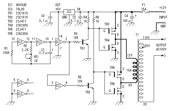
With the values shown the circuit generates a 2-MHz symmetrical square wave. Changing capacitors Cl and C2 to 0.01 µ¥ results in a frequency of 500 Hz. For the particular integrated circuits and power supply voltages (5.0 V), the reliable operating range of Rl = R2 is 2 k ohm to 4 k ohm.
20 Watts Power Amplifier circuit can be made with an IC power amplifier LM1875. IC LM1875 is a single chip power amplifier from National. 20 watts audio amplifier with LM1875 is a low power amplifier with good quality to the room.
To assemble the amplifier 20 watts with IC LM1875 component is not needed much support. 20 watts power amplifier using LM1875 IC in this article using symmetrical power supply. The series of 20 watts audio power amplifier with IC LM1875 can be used as an experiment or first project for the reader, because it is simple and assembly of high success.
Schematic Amplifier LM1875
LM1875 amplifier circuit with the above may result in the strengthening of the voltage up to 27dB for each channel (1 channel 1 IC). Strengthening the voltage can be changed by changing the feedback that is R5 R (on the circuit above using R 22K). But the tension reinforcement can not be less than 20 dB because it can cause oscillation. For the power supply or power supply 20 watts power amplifier rngakaian with lm1875 can use travo 2-3A with CT.
Genius Mouse DX-BlueEye ECO is the world’s first wireless mouse without batteries for PC & Mac users. No battery? Yes, the secret is the use the of the built-in capacitor (gold capacitor) that replace the battery and can be used up to 100,000 times refill.
According to Genius, all we need simply refill it for 3 minutes then the mouse can be used for a full day. With Genius Mouse DX-BlueEye ECO, it means we do not need extra money to purchase external battery pack and also preserve the environment. Genius Mouse DX-BlueEye ECO is using a frequency of 2.4 GHz and can be used within a maximum distance of 15 m and have a 800/1600 dpi. it will be sold with price of $ 39.99.
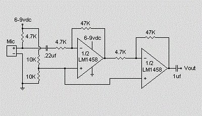
This is a simple preamplifier circuit for electret condenser microphone. using a LM1458 dual op amp IC. The circuit takes the audio signal rom the condenser microphone and amplifier it, so you can use the microphone as the input to some device which wouldn’t normally accept microphone level signals .
Schematic Circuit of Microphone Electret Condenser Pre Amplifier
The circuit requires a 6-9 volt supply. Output of the microphone amplifier can be made variable by connecting a 10kΩ potentiometer . Circuit’s gain can be increased by men perbesar the value of 47K, depending on the input sensitivity of the main amplifier system. The microphone should be housed in a small round enclosure.
Absolute maximum ratings of LM 1458 IC Supply Voltage : ±18V Power Dissipation : 400 mW Differential Input Voltage : ±30V Input Voltage : ±15V Output Short-Circuit Duration: Continuous Operating Temperature Range : 0°C to +70°C Storage Temperature Range : −65°C to +150°C Lead Temperature :(Soldering, 10 sec.) 260°C
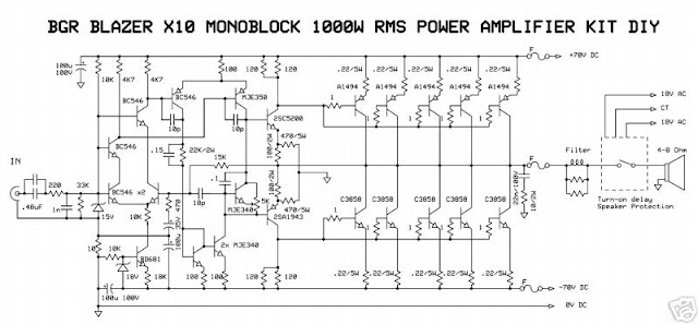
This is a audio power amplifier Blazer circuit provides up to 1000Watt . This fascinating routes several sensible bass and treble alive.
Importantly ought to opt for Power offer supply, that has been fairly high voltage category 70Vdc GND -70V 10A is that the current low level.
The transistors are 2SC3858 (NPN) and 2SA1494 (PNP), and have high bandwidth, wonderful safe operating space, high linearity and high gain. Driver transistors are 2SC5200 (NPN) and 2SA1943 (PNP). All devices are rated at 230V, with the facility transistors having a 150W dissipation and also the drivers are 50W.
This circuit describes an amplifier, power offer and tests procedures that are all inherently dangerous. Nothing described during this article ought to even be thought-about unless you're totally experienced, grasp specifically what you're doing, and are willing to require full 100% responsibility for what you are doing. There are aspects of the look which will need analysis, fault-finding and/or modification.


")
")