Showing posts with label Booster. Show all posts
Showing posts with label Booster. Show all posts
Wednesday, 15 February 2017
Booster BLW 60
In this post an opportunity, I upload booster BLW 60 which may be an inspiration to create home brew. Here I include a file layout that can be unlocked via software sprint layout. of course the software you can download here as well. ok g tuk need to talk at length, immediately wrote download the full data here


Tuesday, 27 December 2016
Booster amplifier circuit
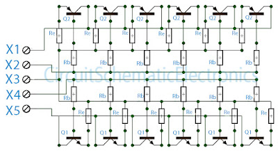
The above circuit is a circuit of booster amplifiers or amplifier end of a power amplifier circuit, Circuit over in the most important influence whether or not , and many more are affected in this final series. Because the booster circuit is the amplifier end of the work was too heavy components causing the rapid component of the heat. If we are wrong then consequences will install components that can cause fatal damaged direct component , such us the installation of pin emiter, collector , and base everything must be correct. In the circuit above can strengthen booster amplifier with maximum work and everything is evenly split, what is it evenly split ? evenly split the point here is that all components can work with the same voltage and the heat evenly , this is because at each respetive base transistor were given the same constrains and same wattage resistor. And to maintain if the power output is too large then the resistor on Re will hamper so that the transistor is not easily broken.
Part List :
Rb=10R/1W
Re=0,5-1R/5W
Q1=Transistor power NPN such us 2N3055 , TIP3055,TIP120,TIP142,2SC2922 , etc.
Q2=Transistor Power PNP such us MJ2955 ,TIP2955,TIP125,TIP147,2SA1216, etc.
X1=Voltage connector (-)
X2=PNP Base connector
X3=Speaker connecor but also must be connected from the buffer
X4=NPN base connector
X5=Voltage connector (+)
Sunday, 25 December 2016
Bass Booster with TL072
The following is megabass circuit schematic (rangkaian megabass) . The megabass circuit is a modified Baxandall tone control with no bass cut and no treble control. It boosts frequencies from about 30Hz to 160Hz can boost by 14dB.
Bass Booster Schematics

Note:
The input capacitor can be replaced with a .01uf cap if you wish.
The 10pf capacitor is optional and will start rolling off everything over 15kHz. 5pf will double this to 31kHz.
The tone control requires a low impedence input. If you already have a low impedence input, the input buffer can be removed. However, the output is inverted.
The opamp is not critical. A 4558 would be just fine.
I do not show the parts for the +4.5 reference. Here is the +4.5 voltage divider I used.
IC A4558 Pinning
The A4558 is a monolithic Integrated Circuit designed for dual operational amplifier.
Absolute maximum ratings of A4558 Ap-amp
Supply voltage VCC 20 or ±10 V
Differential input voltage VIND 20 V
Input voltage VIN ±10 V
Power Dissipation PD 300 mW
Operating temperature Topr -45 ~ +85 °C
Storage temperature Tstg -55 ~ +150 °C
Subscribe to:
Posts (Atom)