The MAX16834 is a neat little chip (it's not the only one, there are plenty of others out there) that allows high efficiency designs for LED string driving. It provides a platform for a Buck or Boost converter design, as well as brightness adjustment via analog/PWM input pins, as well as a fault output (in case of open/short circuits for example) and also diverse other functionalities that can be quite useful.
Showing posts with label Led. Show all posts
Wednesday, 29 March 2017
Simple LED Driver Design
The Simple LED Driver Design TCA62735AFLG is a charge pump type DC DC Converter specially designed for constant current driving of white LED. IC can outputs LED current 120mA or more to 2.8-4.2V input. IC observes the power-supply voltage and the output voltage, and does an automatic change to the best of step up mode 1, 1.5 or 2 times. It is possible to prolong the battery longevity to its maximum.This IC is especially for driving back light white LEDs in LCD of PDA, Cellular Phone, or Handy Terminal Equipment.
This electronic project t LED driver is very simple and require few external electronic parts. Due of simplicity of this circuit this project not require additional explanations . If you want to change this design , please consult the manufactured datasheet.
Some features of the TCA62735AFLG electronic project are Switching Frequency : 1MHz(Typ.), Output Drive Current Capability : Greater than 120mA , 4 Channels Built in Constant Sink Current Drivers, Sink Current Adjustment by External Resistance, Soft Start Function , Integrated protection circuit TSD (Thermal Shut Down) .
Saturday, 4 March 2017
KONKA LED40 F3300C– KONKA LED42F3300C KONKA LED32F3300C – SMPS AND LED BACK LIGHT DRIVE – SCHEMATIC
Used ICs: FAN6755W smps control – 10N60L-B SMPS switching – OZ9902C back-light led drive control
Thursday, 16 February 2017
Simple LED flasher circuit using NE555 timer IC
This circuit consumes more power, but it's advantage is when you need a variable flash rate, like for strobe circuits. You can actually use this circuit as a remote control for strobes that have a remote input. Of course, it has many other applications besides strobes.
- R1, R2, C1 and the supply voltage determine the flash rate. Using a regulated power supply will do much to insure a stable flash rate. For a variable flash rate, replace R1 with a 1 megohm pot in series with a 22k resistor.
- The duty cycle of the circuit (the percentage of the time LED 1 is on to the time it is off during each cycle) is deterimed by the ratio of R1 to R2. If the value of R1 is low in relationship to R2, the duty cycle will be near 50 percent. If you use both LEDs, you will probably want a 50 percent duty cycle. On the other hand, if R2 is low compared to R1, the duty cycle will be less than 50 percent. This is useful to conserve battery life, or to produce a strobe type effect, when only LED1 is used.
- The NE555 timer chip can be damaged by reverse polarity voltage being applied to it. You can make the circuit goof proof by placing a diode in series with one of the supply leads.
- The purpose of R3 and R4 is to limit current through the LEDs to the maximum they can handle (usually 20 milliamps). You should select the value of these according to the supply voltage. 470 ohms works well with a supply voltage of 9-12 volts. You will need to reduce the value for lower supply voltages.
- Rainbow Kits offers several kits to build the above circuit. You can also order these kits from RadioShack.com. The Radio Shack catalog numbers (and web pages) are as follows: standard kit with two 5mm red LEDs, (990-0067), kit with two red, two green and two yellow 3mm LEDs, (990-0063), kit with jumbo green LEDs, (990-0048), kit with jumbo red LEDs, (990-0049). You can also buy all the parts to build the circuit at your local Radio Shack store, including a circuit board (276-159B).
I have built a miniature strobe circuit as follows. Use a 250k pot in series with a 4.7k resistor for R1. The 4.7k resistor sets the upper flash rate limit. Use 2.2k for R2. That sets a really short duty cycle. For this circuit, you don't use LED 2 or R4. For LED 1, I used a two Radio Shack white LEDs in series and no R-3. The circuit runs on a 9 v battery. link
Wednesday, 15 February 2017
Led Flasher Type of Police Circuit Diagram
This is the simple Led Flasher Type of Police Circuit Diagram. LED flasher same as that used in the police car, where the pace at which the lights flash is well paced and there is a sequence on each side. This type of flasher is also called strobe light or stroboscopic light. I began to develop a project to be published here, but by coincidence I ended up finding a circuit, easy to build and giving effect was wanting.
The electronic circuit flasher police is a Russian site, as the Russians have their own markup for semiconductor like this project, which uses KT815 transistors, for sure you will not find these transistors in a Western store, but of course are the replacements, in this case BD135.
Led Flasher Type of Police Circuit Diagram
Flasher LED Police type
This circuit is a classic of electronics, a flip-flop circuit, "astable multivibrators", this circuit is used for common flasher, but in this case two of this circuit were coupled to give the desired effect. The circuit flasher is so simple that can be done by a novice, as we see in the image below of the author, it was made on a standard printed circuit board.
How does the flasher Police
The flasher consists of two astable multivibrators, a leading astable formed by VT1 and VT2 transistors that generate the strobe and VT3 eVT4 transistors that have created short pulses to VT1 and VT2. The master oscillator is switched alternately strobe generator and the operating frequency of the generator is determined by the capacitors C1 and C4 and resistors R5, R6, R8 and R9.
You can use the trimpot R7 and R10 resistors to change the frequency of multivibrators, changing the frequency of blinking of the LEDs. The power transistors VT1 and VT3 and resistors R1 and R2 depend on the power of the LEDs used in the circuit.
Have the circuit power supply can be made with voltages 6-9 V, and its consumption is very low, enabling the use of batteries or battery. You can also change the operating voltage to 12 volts, just change some circuit resistors or put a 7809 regulator in input voltage.
Flasher LED type Police
I will give the most common equivalent found, the VT1 and VT2 transistors can be replaced by medium power transistors BD135, BD137 or BD139. The VT3 transistor can be replaced by transistors average power transistors BD136, BD138 or BD140.
But the transistor VT4 can be replaced by transistor 2sa611, BC556 or 2N4058 and other BCs of life. Below the video of the flasher police, the circuit can also be used for security systems, emergency flashing, holiday lighting, etc.
You can use higher power LEDs in this circuit since modify the resistors R1 and R2.
Friday, 6 January 2017
LED Christmas Lights Circuit
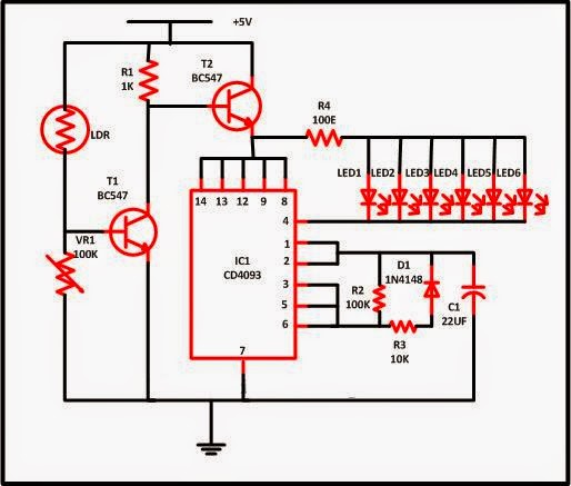
Christmas is known as the carnival of lights and every person decorates its house with multicolored lights which we normally purchase from the market. Did you ever have a thought of building your own Christmas lights, which is used to decorate own house or your own house holy place. This very easy circuit will assist you to develop your own decorative lights.The plus point of these circuits is that you did not require to take tension regarding the ON and OFF of the light. In the evening time, lights automatically become ON while in the morning, it becomes OFF. So it will save your electricity bill when you go away from your house.
Thursday, 5 January 2017
Tuesday, 6 December 2016
Build a LED Matrix Horizontally Circuit Diagram
LED Matrix Horizontally The circuit in this Design Idea shows an unconventional way to use a 5×7 LED matrix.You can use a design containing a set of 5×7 LED units without changing anything in the circuitry, except for the arrangement of the LED units.
LED Matrix Horizontally Circuit Diagram
Using one 5×7 LED matrix, or N units, horizontally instead of vertically allows the display of two characters, or 2×N characters. The minimum pattern for lowercase and uppercase letters requires only a 3×5 LED configuration, except for the letters M and m, which require at least a 5×5 LED configuration and need a dedicated subroutine.
The circuit in Figure 1 uses an 8-bit, 18-pin PIC microcontroller and a decade counter to drive one or two 5×7 LED units to provide a display module of two or four digits. The circuit uses a small pushbutton switch to increment the counter. By default, the circuit works in high-brightness mode. If you press the pushbutton during power-on, the circuit works in low-power mode.
Sunday, 4 December 2016
Simple Led Flasher Circuits Diagram
Simple Led Flasher Circuits Diagram, These 2 circuits can flash a LED terribly bright and consume but 2mA average current. The second circuit permits you to use a high power NPN transistor because the driver if a number of LEDs have to be compelled to be driven. The second circuit is that the basis for a straightforward motor speed management. See note on 330k in Flashing 2 LEDs below.
Simple Led Flasher Circuit Diagram
FLASHING 2 LEDS
These 2 circuits can flash 2 LEDs terribly bright and consume but 2mA average current. They need 6v provide. The 330k might have to be 470k to provide flashing on 6v as 330k activates the primary transistor an excessive amount of and also the 10u doesn't flip the primary transistor off alittle quantity when it becomes totally charged and so cycling isn't made.
Simple Led Flasher Circuit Diagram 2
Thursday, 3 November 2016
6 Channel LED Driver with MCP34845
This 6 channel LED driver circuit is designed using MCP34845 ic manufactured by Frescale Semiconductor with integrated power supply . The MCP34845 6 channel LED driver circuit operates from 5 to 21 volts and is specially designed for use in backlighting LCD displays from 10” to 17”+ for devices like: PC Notebooks, Netbooks, Picture Frames, Portable DVD Players , Small Screen Televisions , Industrial Displays, Medical Displays, etc.
6 Channel LED Driver Circuit Diagram:
The MCP34845 LED driver is capable of driving up to 16 LEDs in series in 6 separate strings. PWM dimming is performed by applying a PWM input signal to the PWM pin which modulates the LED channels directly.
Main features of this driver electronic project are : input voltage of 5.0 to 21 V , boost output voltage up to 60 V, 2.0 A integrated boost FET , fixed boost frequency - 600 kHz or 1.2 MHz , OTP, OCP, UVLO fault detection , LED short/open protection , programmable LED current between 3.0 mA and 30 mA.
Subscribe to:
Posts (Atom)