Showing posts with label to. Show all posts
Showing posts with label to. Show all posts
Saturday, 25 March 2017
How to use LEDs introduction
ladyada.net has write a new article on how to use LEDs for people making their first steps on electronics. It talks about LED polarity, the various kinds of LEDs, what are LEDs used for, changing the brightness with resistors, changing the brightness with voltage, learn how to calculate the current limiting resistor etc.

[ ]

Saturday, 18 March 2017
How to control LM2596 buck converter with microcontroller
Every now and then someone asks on different forums if there is an way to control cheap LM2596 modules with an Arduino or another microcontroller. I decided to demonstrate one solution that might be basic electronics for some, but still many don’t know about.

Those buck converters will change the output voltage to make the feedback pin, connected to the output via a voltage divider, become 1.25V or so. If feedback is higher, output gets lower and vice versa. If one changes the ratio of resistors in voltage divider, output voltage will change. This is usually done by turning a trimmer resistor with a screwdriver. That is good enough for many applications where voltage will be set only once, but sometimes there is a need to adjust the output voltage more frequently.[ ]
Thursday, 16 March 2017
Simple Project to Build A Video Signal Emphasis
With this circuit we can amplification selectively the high signal of picture frequencies [Video] with result bigger clarity than this. The circuit should be placed between a Video unit and the reception Scart or the plug Video input of television receiver. The designing is simple, it’s based in three only transistor.
Video Signal Emphasis Circuit Diagram

The first stage of Q1 function as isolator - adapter of input impedance. The second stage round the Q2 in common base connection which the gain is determined by the TR2. The TR1, R6 and C3 determine the frequency response. The third stage round the Q3 works as output buffer and 75-ohm line driver. The TR2 should be regulated in a place where the circuit output voltage, to be 1Vp-p, in 75 ohm load. The circuit functions with 12Volts - 50mA well stabilized.
Part List
R1=82ohm
R2=5.6Kohm
R3-9-11=2.7Kohm
R4=330ohm
R5=220ohm
R6=470ohm
R7=270ohm
R8=12Kohm
R10=2.2Kohm
R12=180ohm
R13=68ohm
C1-4-5=100uF 16V
C2=2200uF 16V
C3=470pF ceramic
C6=470uF 16V
C7=220uF 16V
C8=100nF 100V MKT
TR1=250ohm trimmer
TR2=500ohm trimmer
D1=1N4148
Q1-2-3=BC547
J1-2=Female RCA jack
J3=2pin connector 2.54mm step
Video Signal Emphasis PCB

Video Signal Emphasis Circuit Diagram
The first stage of Q1 function as isolator - adapter of input impedance. The second stage round the Q2 in common base connection which the gain is determined by the TR2. The TR1, R6 and C3 determine the frequency response. The third stage round the Q3 works as output buffer and 75-ohm line driver. The TR2 should be regulated in a place where the circuit output voltage, to be 1Vp-p, in 75 ohm load. The circuit functions with 12Volts - 50mA well stabilized.
Part List
R1=82ohm
R2=5.6Kohm
R3-9-11=2.7Kohm
R4=330ohm
R5=220ohm
R6=470ohm
R7=270ohm
R8=12Kohm
R10=2.2Kohm
R12=180ohm
R13=68ohm
C1-4-5=100uF 16V
C2=2200uF 16V
C3=470pF ceramic
C6=470uF 16V
C7=220uF 16V
C8=100nF 100V MKT
TR1=250ohm trimmer
TR2=500ohm trimmer
D1=1N4148
Q1-2-3=BC547
J1-2=Female RCA jack
J3=2pin connector 2.54mm step
Video Signal Emphasis PCB
Wednesday, 15 March 2017
Square A to Sine Wave Converter Circuit Diagram
Build a Square A to Sine Wave Converter Circuit Diagram. This is a simple circuit diagram in this circuit using Two pairs of MOSFETs form a bridge that alternately switches current in opposite directions. Two parallel-resonant LC circuits complete the converter. The Ll/C1 combination is resonant at the fundamental frequency; the L2/C2 combination is resonant at the clock frequency`s third harmonic and acts as a trap.
Square A to Sine Wave Converter Circuit Diagram

Tl and C3 ensure that both halves of the MOSFET bridge are never on at the same time by providing a common delay to the gate drive of each half. Select the values of R1 and C3 to yield a time constant that`s less than 5% of the clock`s period. You can add an output amplifier for additional buffering and conditioning of the circuit`s sine-wave output.
Sunday, 12 March 2017

Friday, 10 March 2017
Lead achid battery charger up to 3 battery
See battery charger circuit below :
 | |
| This is charger battery circuit |
Above circuit furnishes an initial voltage of 2.5 Volt per Cell at 25 degree celcius to rapidly charge a battery . the charging current decreases as the battery cahrges , and when the current drop 180 mA , the charging circuit reduces the output voltage to 2.35 V per cell, leaving the battery in a fully charged state.
Wednesday, 8 March 2017
How to build Digital Step Km Counter Circuit Schematic
Description
This circuit measures the distance covered during a walk. Hardware is located in a small box slipped in pants' pocket and the display is conceived in the following manner: the leftmost display D2 (the most significant digit) shows 0 to 9 Km. and its dot is always on to separate Km. from hm. The rightmost display D1 (the least significant digit) shows hundreds meters and its dot illuminates after every 50 meters of walking.
A beeper (excludable), signals each count unit, occurring every two steps. A normal step was calculated to span around 78 centimeters, thus the LED signaling 50 meters illuminates after 64 steps (or 32 operations of the mercury switch), the display indicates 100 meters after 128 steps and so on.
For low battery consumption the display illuminates only on request, pushing on P2. Accidental reset of the counters is avoided because to reset the circuit both pushbuttons must be operated together. Obviously, this is not a precision meter, but its approximation degree was found good for this kind of device. In any case, the most critical thing to do is the correct placement of the mercury switch inside of the box and the setting of its sloping degree.
Circuit diagram:

Parts:
- R1 = 22K 1/4W Resistor
- R2 = 2.2M 1/4W Resistor
- R3 = 22K 1/4W Resistor
- R4 = 1M 1/4W Resistor
- R5 = 4.7K 1/4W Resistor
- R6 = 47R 1/4W Resistor
- R7 = 4.7K 1/4W Resistor
- R8 = 4.7K 1/4W Resistor
- R9 = 1K 1/4W Resistor
- C1 = 47nF 63V Polyester Capacitor
- C2 = 100nF 63V Polyester Capacitor
- C3 = 10nF 63V Polyester Capacitor
- C4 = 10µF 25V Electrolytic Capacitor
- D1 = Common-cathode 7-segment LED mini-display (Hundreds meters)
- D2 = Common-cathode 7-segment LED mini-display (Kilometers)
- Q1 = BC327 45V 800mA PNP Transistors
- Q2 = BC327 45V 800mA PNP Transistors
- P1 = SPST Pushbutton (Reset)
- P2 = SPST Pushbutton (Display)
- IC1 = 4093 Quad 2 input Schmitt NAND Gate IC
- IC2 = 4024 7 stage ripple counter IC
- IC3 = 4026 Decade counter with decoded 7-segment display outputs IC
- IC4 = 4026 Decade counter with decoded 7-segment display outputs IC
- SW1 = SPST Mercury Switch, called also Tilt Switch
- SW2 = SPST Slider Switch (Sound on-off)
- SW3 = SPST Slider Switch (Power on-off)
- BZ = Piezo sounder
- B1 = 3V Battery (2 AA 1.5V Cells in series)
Circuit operation:
IC 1A & IC 1B form a monostable multi vibrator providing some degree of freedom from excessive bouncing of the mercury switch. Therefore a clean square pulse enters IC2 that divides by 64. Q2 drives the LED dot-segment of D1 every 32 pulses counted by IC2. Either IC3 & IC4 divide by 10 and drive the displays. P1 resets the counters and P2 enables the displays. IC1C generates an audio frequency square wave that is enabled for a short time at each monostable count. Q1 drives the piezo sounder and SW2 allows disabling the beep.Notes:
- Experiment with placement and sloping degree of mercury switch inside the box: this is very critical.
- Try to obtain a pulse every two walking steps. Listening to the beeper is extremely useful during setup.
- Trim R6 value to change beeper sound power.
- Push P1 and P2 to reset.
- This circuit is primarily intended for walking purposes. For jogging, further great care must be used with mercury switch placement to avoid undesired counts.
- When the display is disabled current consumption is negligible, therefore SW3 can be omitted.
Source http://www.extremecircuits.net/2009/12/digital-step-km-counter-circuit.htm
Friday, 3 March 2017
Simle DC to AC Inverter by IC 555
This be basic AC inverter Circuit. Convenient for the initiator who have to is extremely fond of something experience. Because of use IC 555 highly popular, perform produce the frequency ,then enlarge with transistor NPN and PNP number TIP41 and TIP42 drive the coil transformer. Get by can pay Voltage output about 120V to 230V at frequency 50Hz. By have R4 perform control the frequency and should use. Voltage supply about 5V to 15V the detail sees in circuit picture sir.
Simple DC to AC Inverter by IC 555 Circuit Diagram

Thursday, 16 February 2017
Simple 500W 12V to 220V Inverter
500W 12V to 220V Inverter Circuit Diagram

This is a 500W DC-to-AC inverter circuit diagram which produces an AC output at line frequency and voltage. 12VDC to 220V 50Hz inverter circuit will power 220V or 110V appliances from 12V car battery. The circuit is easy to make and is low cost. Use proper transformer. The output (in watts) is up to you by selecting different power rating transformer and power transistor rating. If you load electronic device which require 120V AC, then use transformer with 120V in output.
Sunday, 22 January 2017
How to make a guitar cable
Today we're going to do a quick run through of how to make a guitar cable. It’s a pretty simple procedure, but if you’ve never made one before, it can be a little bit daunting at first.
To make a cable, you will need to following items:
- Some cable
- Two ¼” jack plugs
- A soldering iron and some solder
- Wire cutters/strippers/pliers
Here’s the cable we're going to use:

And we're going to use two of these jack plugs:

I really like this design of plug (and I’ve used a tonne of different ones over the years). To open it, you unscrew the end cap/cable relief:

Then lift up the cover:

Which reveals the following:

Obviously you can use a different design if you like.
Today we're making a short cable that will go between effects pedals. There’s nothing different between this sort of cable and a standard guitar cable, apart from the length.
This one, we're going to cut to 20cm (8”):

Then trim the outer sleeve back by 15mm (a little under 5/8”):

We trim the inner wire insulation back by a few mm and then twist the end of the wire together. The outer shielding wiring is also gathered and twisted together:

All of this is done at both ends, leaving us with this:

We then slide any necessary items over the cable before doing any soldering. You’ll get away with forgetting this for the first plug, since you can always slide it on from the other end after soldering. However, for the second plug, it’ll be too late and you’ll have to unsolder something to fix it.

Next step is to melt a couple of healthy blobs of solder onto the two positions where we intend to attach wires.

Then we “tin” the wires, which is to say, we melt a little bit of solder onto them:

We're also going to cut the outer ground wire a little shorter, so that it fits its position on the plug better:

Now we solder the wires on. When doing this, try not to keep the soldering iron on the plug for an extended amount of time, as some of them can be ruined very easily.
Firstly, the ground wire:

And then the positive/tip wire:

Before closing up, we need to secure the cable by tightening the metal clamp as follows:

Then we place the cover back in place:

And tighten the end plug/cable relief:

We do the same for the other end of the cable:

And here’s the end result:

Saturday, 21 January 2017
LT3582 12 DC 5V to 12V DC Converter Circuit Diagram
Using LT3582-12 dual channel DC DC converter integrated circuit, manufactured by Linear Technology, can be designed a very simple step up dc converter. This 5 to 12V c converter electronic project provide both positive and negative outputs required in many biasing applications such as active matrix OLED (organic light-emitting diode)displays as well as CCD (charge coupled device) applications.
LT3582-12 DC 5V to 12V DC Converter Circuit Diagram
LT3582-12 DC 5V to 12V DC Converter Circuit Diagram

Wednesday, 28 December 2016
DC to AC converter 12 to 100 Voltage circuit with IC
An AC-DC voltage converter with electrically isolated with onput and output circuits and converters with a transformer with at least one primary coil and a capacitor resonance said coil to at least one primary school.
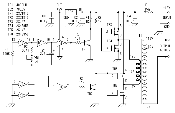
A switching transistor whose collector-emitter path is connected in series at least a coil and the primary school to the transistor switching system for the storage in the database of the surface sensors.
switching power transistor provides the foundation for the transistor switching system, and by other means in order to increase the voltage transmitter Collector of the transistor switching and deliver a response to such an increase and at least in the period immediately after the increase.
one while driving for the transistor circuit, the additional base current is very progressive with a predetermined, so that the storage of the relatively constant switching transistor in the beach for the operation of the converter.
Tuesday, 27 December 2016
Structured Text Tutorial to Expand Your PLC Programming Skills

Do you also struggle reading your own and others huge ladder diagrams?
The truth is, that even though ladder diagram (LD) is an easy programming language for beginners, it can be very hard to read and understand. That’s why Structured Text is a better PLC programming language, and you can learn it in this tutorial.
It can be almost impossible to find head and tail in a larger PLC program written in ladder logic. So, what might seem easy to learn (especially for technicians and electricians) is not always the best thing to program in. Your ladder diagram will be hard to understand for others than yourself.
How can I be sure about that? Try it yourself. Take a look at one of these ladder logic examples, and see how long it takes to understand it. See my point?
Luckily for us there’s a better PLC programming language available. It’s called Structured Text.
At first, it may seem better to use a graphical programming language for PLC programming. But in my opinion, that is only true for smaller PLC programs. By using a text-based PLC programming language, your program will take up much smaller space, and the flow/logic will be easier to read and understand.
Another advantage is that you can combine the different programming languages. You can even have function blocks containing functions written in Structured Text. The fact that this is a standardized programming language also gives us the option to program different PLC brands with Structured Text. Probably the most common PLC (in Europe at least) is the Siemens S7 PLC’s. They can be programmed with Structured Text and you can start already now with the Siemens S7-1200 Starter Kit, which is also a great kit to get you introduced to the Siemens PLC environment.
But on the other hand, if you have never seen a high-level programming language, Structured Text can be a great introduction to those languages and the syntax used.
Before you read this tutorial I recommend that you take a brief look at this PLC program written in Structured Text. Try to see if you can understand the function of this program. Does Structured Text look familiar to you?
Starting with the example above, you can see that the whole program begins with PROGRAM and ends with END_PROGRAM. Everything in between is your PLC program. These two words are the delimiting keywords for program declarations. More on keywords later.
Don’t be confused about the END_PROGRAM, because your program won’t end completely here. When the PLC reaches the END_PROGRAM the PLC scan cycle will start over again, and your program will repeat itself.

This is just like ladder logic or any other PLC programming language – it will run over and over again. And if you are used to programming microcontrollers, the PROGRAM/END_PROGRAM will be similar to the infinite loop in C.
NOTE:
One thing to add here is that, when you are programming in Structured Text, you will often not use the PROGRAM/END_PROGRAM construct. It will already be done by the PLC programming software, and the code you have to write, is what you want inside that construct.
The flow control of PLC programs written in Structured Text is the same as in ladder logic: execute one line at a time.
As you can see in the example, Structured Text is full of colons, semicolons and other symbols. All these symbols has a meaning and is used to represent something. Some of them are operators, some are functions, statements or variables.
All the details of the syntax will be explained as you move through this tutorial. But there are some general rules for the syntax of Structured Text you should know about. You don’t have to memorize all the syntax rules for now, as you will when you get your hands into the programming:
What’s really important to understand here is that, when you write a PLC program in Structured Text, your computer will translate that to a language the PLC can understand.
When you upload the Structured Text PLC program to your PLC, the programming software you use will compile your program. This means that it will translate the code to a sort of machine code which can be executed by the PLC.
The compiler uses the syntax of the programming language to understand your program.
For example: Each time the compiler sees a semicolon, it will know that the end of the current statement is reached. The compiler will read everything until it reaches a semicolon, and then execute that statement.
Comments are good, and as a beginner you should always comment your code. It makes it easier to understand your code later.
In Structured Text you can make either one line comments or multiple line comments.
Single line comment:
Take this little story in chapter 2.4:
Although this might be put on the edge, you should always write your code so it is as easy as possible to understand. Even without comments. You start doing this by simply making the code easy to read with spaces.
But for now, you should not worry about comments. Make as many as you want while you are still a beginner.
You probably know statements as something coming from humans. You can make a statement, a president or even a company can make a statement. And in PLC programming, statements are almost the same.
Let’s take the first statement as an example:
In this statement you are telling the PLC to create a variable called X and that variable should be a BOOL type.
Both the PROGRAM/END_PROGRAM and VAR/END_VAR are constructs, meaning that they delimit a certain area in your program for something specific. The PROGRAM construct is where all your PLC program is, and the VAR construct is where you define variables.
All the four are called keywords, because they are reserved words. You can’t use those words for anything else when you are programming in Structured Text. The name of your program cannot be PROGRAM or even program (STL is not case sensitive), because that word can only be used to make a construct to delimit your PLC program.
Back to variables…
If you know other programming languages, chances are that you know about variables already.
But if you don’t, here’s an introduction to variables you probably will like:
A variable is a place where you can store data.
Depending on what type of data you want to store, there are several data types available. The different kinds of data are called data types. For example, if you have a variable where you want to store either TRUE or FALSE, you can declare it as a BOOL type.
The BOOL type is a boolean data type which means that it can contain a boolean value (TRUE or FALSE).
Now, that was two thing about variables. They have a certain data type, and they contain a value of that data type. But there’s one more thing you can control in your variables. The name of the variable.
To make it easy for you to use your variables throughout your PLC program, they all have names. When you define a variable in the VAR construct, you start by giving the varible its name:
Be aware, that when you are programming with some PLC software like Siemens STEP 7 or Rockwell you won’t use the VAR/END_VAR til declare variables. Instead variables are often called tags or symbols, and even though you are programming in Structured Text, you declare them visually (like in the image below) or in a function block.

But no matter what variables are called, they always have the same function. And with IEC 61131-3 Programming software like STEP 7, Codesys or Studio 5000, the standard data types will always be available.
All the standard data types are defined by the PLCOpen Organization and they are part of the PLC programming languages. Every PLC programming software with Structured Text has these data types included. In the IEC standard the data types are divided into two categories: Elementary data types and derived data types.
Elementary data types
Under each elementary data types there are several IEC data types available. These are the data types defined in IEC 61131-3:
Integers:
Floating points:
Time:
Strings:
Bit strings:
Derived data types
The derived data types are your own custom data types. All the derived data types are built by making a construction of the keywords TYPE and END_TYPE. In between the keywords is the kind of derived data type you want to declare.
All these different data types might seem a little overwhelming for now. Especially if you haven’t used a textual programming language before. But there’s no need to worry.
For now, you only have to remember a few of them to get started programming with Structured Text. As you get better and your programs more complicated, you will gradually learn about more data types as you use them. What’s important here is that you don’t move ahead too fast. You want to get the basics right.
As you can see the different data types can hold different data formats and thereby different values.
But how do you put the values in the variables? And how do you use the variables?
With statements and operators.
Just like operators, expressions are a crucial part of programming languages.
An expression is a construct that, when evaluated, yields a value.
This means that when the compiler compiles an expression, it will evaluate the expression and replace the statement with the result. Take this example with the two variables A and B.
A contains the value 10 and B contains 8.
An expression are composed of operators and operands.
So what are operators and operands?
Since, you just saw an example of an expression, you just saw both an operator and two operands. A and B are both operands and the + is an operator.

Remember that operators are used to manipulate data. That is exactly what the + is doing. It is taking the value of the variable A and adding it to the value in B.
The + is also called the addition operator because the operation is addition.
All the operators in the table above are sorted after precedence. This is also called order of operations, and you may know about if from mathematics.
The order of operations is the order in which the operations are executed or calculated. Just take a look at this expression:
As you can see in the table of operators the operator with the highest precedence is parenthesis. This means that the first thing, that will be evaluated, is everything in parenthesizes – in this example: (C, D).
But since MAX(C, D) is actually a function, we can jump one row down in the table to function evaluation.
So, in the above expression, the first thing that will be evaluated is the function: MAX(C, D). The function will yield (replace the function) with the answer. Which in this case is the highest of the two variables C and D.
Let’s image C is the result. The expression will now look like this:
There are two operations left: multiply and addition. But since multiply has a higher precedence, that will be the first to be evaluated.
B * C comes first and then the result is added to A.
Every time an expression is evaluated, the evaluation follows the order of precedence as in the table above.
Example:
3
Example:
FALSE
Example:
TRUE
Example:
15
Since this operation is bitwise the calculation will be per bit. So to understand what’s going on here, you have to convert the numbers to binary values:
15 = 1111
8 = 1000
Now each bit in the number 1111 (15) can be used in a logical operation with the other number 1000 (8):
But what if you want the PLC (compiler) not to evaluate something, but to DO something?
Statements are the answer.
As I mentioned previously in this article, statements are you telling the PLC what to do. It’s the instruction you give the PLC to take action.
If you make an expression that yields a result, that won’t do much. Expressions are all the calculations and if you don’t use the results of those expressions in some actions (statements), it will be like buying groceries but not cooking.
Let’s take a look at the actions or statements that you can make in Structured Text.
Beginning with actions, the most fundamental statement in Structured Text is the assignment statement. Statements are also described in the IEC standard developed by PLCOpen, and the first one they list is the assignment statement.
Here’s how an assignment statement looks like:
To take the value of the variable B and put it in the variable A.
The PLC is assigning a value to a variable. Here’s an even simpler example:
Since the value of A is now 10, we can make another statement, but this time with an expression:

The last thing is that the := symbol is called the assignment operator. Yes, it is an operator just like the operators used in expressions. Often those two types of operators are mistaken for each other and used wrong.
A common mistake is to use the equality operator (=) instead of the assignment operator (:=). But even though they look like each other there’s a huge difference. Take these two examples:
If the right side and the left side is equal it evaluates to TRUE or 1. If not, it will evaluate to FALSE or 0.
With some other operators, the equality operator is a relational operator. All the relational operators will evaluate to either TRUE or FALSE.
On the second line you’ll see a statement. This time the operator will be used for an action instead of an evaluation. Assignment is the action, and here the value of A will be given the value of B.
At last, you can always identify a statement by the semicolon. Once again, the semicolon is how the compiler knows when the end of a statement is reached.
You can have all sorts of expressions in your assignment statements, from simple values like numbers to variables and functions. Because all expressions will be evaluated first, and then, the result of that evaluation will be used in the assignment statement.
But let’s zoom out a bit and think about PLC programs. A PLC program is a piece of logic (I call it PLC logic) and therefore has to make some decisions. That’s why we use a PLC or any other controller. To decide and act on the current state.
Simplified: The PLC will look at the states of all the inputs and use your PLC program to decide what outputs to set.
So in your PLC program you need a way to make decisions. This brings us to conditional statements.
Conditional statements are used for exactly that: To make decisions.
There are two ways of doing conditional statements in Structured Text: IF statements and CASE statements.
IF statements are decisions with conditions.
But even though IF-statements are quite simple to understand, you still have to know how to give the PLC the conditional statements. This brings us back to the syntax.
There’s a special syntax for IF statements. This means, that you have to write it in a certain way for the compiler to understand it. Because just like semicolons are used to end statements, there are special keywords to make an IF statement.
Here’s how the syntax for IF statements looks like in STL:
Notice that the syntax for IF statements looks very similar to plain English. The first line contains two keywords: IF and THEN. Between those two keywords are the condition, which is an expression. But not just any expression. A boolean expression.
Boolean expressions are used in IF statements as conditions.
IF the boolean expression evaluates to TRUE, THEN the following statements will be executed.
The PLC will only execute the statements after the keyword THEN, if the expression evaluates to TRUE. This is illustrated by the following example:
See what I just did here?
In the example above a decision was made depending on the value of a variable. Now, even though this was a fairly simple decision, we can already translate that into real PLC programming.
Let’s say you want to make a program that sets a PLC output depending on the state of an input. With a simple IF statement you can do that in Structured Text:
Since, both the INPUT1 and OUTPUT1 variables are of the type BOOL, the first line in the statement could also look like this:
But what if your PLC program requires multiple conditions?
Of course you could write this as multiple individual IF statements. But Structured Text has more options to the IF statements.
Just like most other programming languages you can use the ELSIF and ELSE keywords for multiple conditions in the same IF statement.
Both ELSIF and ELSE are optional in IF statements, but this is how the syntax looks like:
Here it works just like with the IF keyword: If the boolean expression after the keyword is true, the following statements will be executed.
At last is the ELSE keyword. It works as a default option for your IF statement. If all the IF and ELSIF boolean expressions are evaluated to FALSE, the statements after the ELSE keyword will be executed.

What if you want not just 1 but 2 inputs to be TRUE before an output is set. The expression would look like this:
Essentially, CASE statements and IF statements are the same. But CASE statements use numeric expressions instead of boolean expressions. CASE statements also have a slightly different syntax, that makes it more suitable for certain purposes.
This is how the syntax for CASE statements looks like in Structured Text:
As a default option, CASE statements also have an ELSE keyword. The statements after that keyword are executed only if none of the results (or cases) matches the result of the numeric expression.
Here’s a very simple example:
Once again, Code.org has made one of the best introductions to repeating loops. This time, Facebook founder, Mark Zuckerberg uses a little more than a minute to explain repeating loops.
In relation to PLC programming loops can be used for many different purposes. You might have a function or a set of statements that you want to execute a certain amount of times or until something stops the loop.
In Structured Text you will find 3 different types of repeating loops:
Common for all the types of loops is that they have a condition for either repeating or stopping the loop. The condition in FOR and WHILE loops decides whether the loop should repeat or not. But for the REPEAT loop the condition is an UNTIL condition, and it will decide whether the loop should stop or not.
This is the syntax of FOR loops in Structured Text:
FOR
Keyword that starts the FOR loop statement.
count := initial_value
This assignment operation is where you set the initial value you want to count from. Count is the variable name and initial_value is the value you want to start counting from.
TO
Keyword before the value to count up to.
final_value
This is the value you want to count to. Place 100 here and your loop will count up to 100.
BY
Keyword to use custom incremental value.
increment
The value of which you want to increase the count for every time the loop runs. If you set the increment to 10 and the count to 100, the loop will run 10 times.
DO
<statement>;
END_FOR;
This last part between the keyword DO and END_FOR is the statements you want to execute each time your loop runs. These statements will be executed as many times as the loops repeats.
Since FOR loops can only have a preset amount of time they will repeat, that is what they are used for. In PLC programming this could be something as simple as an item that has to be painted/dried four times. A FOR loop that counts to four will work just fine here.
At last you can use an IF statement with the keyword EXIT to stop the loop before the count. You can add a boolean condition that if TRUE stops the loop.
Here’s the syntax of WHILE loops:
When END_WHILE is reached, the boolean expression will be evaluated again. This will happen over and over again until the expression doesn’t evaluate to TRUE. But to make the loop stop at one point, you have to change a value in the boolean expression. Only in that way can the boolean expression go from TRUE to FALSE.
Here’s an example of a WHILE loop in Structured Text:
That is what’s happening in line 3. This is the first statement in the WHILE loop, and with the other statements, are executed each time the loop repeats. In the third line the value of the counter variable is increased by 1. You can say that the incremental value is 1.
In the example above, the loop will repeat 10 times. When the value of count reaches 10, the boolean expression will be evaluated to FALSE (because 10 is not less than 10) and the loop will stop.
You can also use the EXIT keyword in the WHILE loop to stop repeating the loop before the boolean expression is FALSE. The syntax is an IF statement with the EXIT keyword in. Place it anywhere between DO and END_WHILE keywords.
In ST, the syntax for REPEAT loops looks like this:
Just as with the WHILE loops you have to change a value in the boolean expression along the way, to make the loop stop repeating. This can be done be incrementing the value of a variable (to count), or it can be done with a conditional statement like an IF statement inside the loop.
You should write some PLC programs. Because that is the way to really learn Structured Text and master the programming language.
For learners, the biggest advantage of TwinCat 3 is that it has a simulator included. You don’t need to buy a PLC, you just use the soft PLC.
On YouTube there is a free series of videos from SquishyBrained. You should follow him! He even made a video series about his DIY 3D Printer. It’s a great video tutorial to get you started with Structured Text PLC programming in TwinCat 3.
Although there are not many great resources on how to use Codesys for beginners, Brian Hobby has made some amazing tutorial videos.
The first video shows you how to create a new project in Codesys. A little Ladder Logic is also included in the video.
The second video helps you program in Structured Text with Codesys.
I think, that the last part is the most important part. Learning from others with experience can be the most effective way to learn, not just about the programming language, but how to use it.
The truth is, that even though ladder diagram (LD) is an easy programming language for beginners, it can be very hard to read and understand. That’s why Structured Text is a better PLC programming language, and you can learn it in this tutorial.
It can be almost impossible to find head and tail in a larger PLC program written in ladder logic. So, what might seem easy to learn (especially for technicians and electricians) is not always the best thing to program in. Your ladder diagram will be hard to understand for others than yourself.
How can I be sure about that? Try it yourself. Take a look at one of these ladder logic examples, and see how long it takes to understand it. See my point?
Luckily for us there’s a better PLC programming language available. It’s called Structured Text.
What is Structured Text Programming?
Structured Text is PLC programming language defined by PLCOpen in IEC 61131-3. The programming language is text-based, compared to the graphics-based ladder diagram.At first, it may seem better to use a graphical programming language for PLC programming. But in my opinion, that is only true for smaller PLC programs. By using a text-based PLC programming language, your program will take up much smaller space, and the flow/logic will be easier to read and understand.
Another advantage is that you can combine the different programming languages. You can even have function blocks containing functions written in Structured Text. The fact that this is a standardized programming language also gives us the option to program different PLC brands with Structured Text. Probably the most common PLC (in Europe at least) is the Siemens S7 PLC’s. They can be programmed with Structured Text and you can start already now with the Siemens S7-1200 Starter Kit, which is also a great kit to get you introduced to the Siemens PLC environment.
High-level Programming Languages
If you are already familiar with high-level programming languages like PHP, Python and C, Structured Text will seem familiar to you. The syntax of Structured Text is developed to look like the syntax of a high-level programming language with loops, variables, conditions and operators.But on the other hand, if you have never seen a high-level programming language, Structured Text can be a great introduction to those languages and the syntax used.
Before you read this tutorial I recommend that you take a brief look at this PLC program written in Structured Text. Try to see if you can understand the function of this program. Does Structured Text look familiar to you?
PROGRAM stexample
 VAR
 x : BOOL;
 END_VAR
 x := TRUE;
 REPEAT
 x := FALSE;
 UNTIL x := FALSE;
 END_REPEAT;
END_PROGRAM;
The Flow of Structured Text
The first thing you should learn is the structure or the syntax of Structured Text. When you understand the structure, you will understand how the flow of your program works.Starting with the example above, you can see that the whole program begins with PROGRAM and ends with END_PROGRAM. Everything in between is your PLC program. These two words are the delimiting keywords for program declarations. More on keywords later.
Don’t be confused about the END_PROGRAM, because your program won’t end completely here. When the PLC reaches the END_PROGRAM the PLC scan cycle will start over again, and your program will repeat itself.
Structured Text Program Flow.
This is just like ladder logic or any other PLC programming language – it will run over and over again. And if you are used to programming microcontrollers, the PROGRAM/END_PROGRAM will be similar to the infinite loop in C.
NOTE:
One thing to add here is that, when you are programming in Structured Text, you will often not use the PROGRAM/END_PROGRAM construct. It will already be done by the PLC programming software, and the code you have to write, is what you want inside that construct.
The flow control of PLC programs written in Structured Text is the same as in ladder logic: execute one line at a time.
Starting with the Syntax of Structured Text
The syntax of a programming language is the definition of how it is written. To be more precise, what symbols is used to give the language its form and meaning.As you can see in the example, Structured Text is full of colons, semicolons and other symbols. All these symbols has a meaning and is used to represent something. Some of them are operators, some are functions, statements or variables.
All the details of the syntax will be explained as you move through this tutorial. But there are some general rules for the syntax of Structured Text you should know about. You don’t have to memorize all the syntax rules for now, as you will when you get your hands into the programming:
- All statements are divided by semicolons
Structured Text consists of statements and semicolons to separate them. - The language is not case-sensitive
Even though it is good practice to use upper- and lowercase for readability, it’s not necessary. - Spaces have no function
But they should be used for readability.
What’s really important to understand here is that, when you write a PLC program in Structured Text, your computer will translate that to a language the PLC can understand.
When you upload the Structured Text PLC program to your PLC, the programming software you use will compile your program. This means that it will translate the code to a sort of machine code which can be executed by the PLC.
The compiler uses the syntax of the programming language to understand your program.
For example: Each time the compiler sees a semicolon, it will know that the end of the current statement is reached. The compiler will read everything until it reaches a semicolon, and then execute that statement.
Comment Syntax
In textual programming languages you have the ability to write text that doesn’t get executed. This feature is used to make comments in your code.Comments are good, and as a beginner you should always comment your code. It makes it easier to understand your code later.
In Structured Text you can make either one line comments or multiple line comments.
Single line comment:
// commentComment after end of ST line:
<expression>; /* comment */or
<statement>; (* comment *)Multiple line comment:
/* start commentor
...
end comment */
(* start comment
...
end comment *)
Should You Comment Every Detail?
As you gradually get better and better, you should make fewer and fewer comments about the functionality. The reason for this is The Tao of Programming, which is a book about programming inspired by the old Chinese Tao Te Ching. Or actually the principle behind the book is the reason.Take this little story in chapter 2.4:
A novice asked the Master: “Here is a programmer that never designs, documents or tests his programs. Yet all who know him consider him one of the best programmers in the world. Why is this?”
The Master replied: “That programmer has mastered the Tao. He has gone beyond the need for design; he does not become angry when the system crashes, but accepts the universe without concern. He has gone beyond the need for documentation; he no longer cares if anyone else sees his code. He has gone beyond the need for testing; each of his programs are perfect within themselves, serene and elegant, their purpose self-evident. Truly, he has entered the mystery of Tao.”
Although this might be put on the edge, you should always write your code so it is as easy as possible to understand. Even without comments. You start doing this by simply making the code easy to read with spaces.
But for now, you should not worry about comments. Make as many as you want while you are still a beginner.
Making Statements with Structured Text
So, Structured Text consists of statements. But what is statements?You probably know statements as something coming from humans. You can make a statement, a president or even a company can make a statement. And in PLC programming, statements are almost the same.
A statement is you telling the PLC what to do.
Let’s take the first statement as an example:
X : BOOL;The compiler will read this as one statement, because when it reaches the semicolon, it knows that this is the end of that statement. Remember, statements are separated by semicolons. That’s the main syntax rule of this language.
In this statement you are telling the PLC to create a variable called X and that variable should be a BOOL type.
Using Variables in Structured Text
Before we dig deeper into the statement, let me get back to the keywords i mentioned before. As you can see, the variable X is defined in between two other keywords – VAR and END_VAR.Both the PROGRAM/END_PROGRAM and VAR/END_VAR are constructs, meaning that they delimit a certain area in your program for something specific. The PROGRAM construct is where all your PLC program is, and the VAR construct is where you define variables.
All the four are called keywords, because they are reserved words. You can’t use those words for anything else when you are programming in Structured Text. The name of your program cannot be PROGRAM or even program (STL is not case sensitive), because that word can only be used to make a construct to delimit your PLC program.
Back to variables…
If you know other programming languages, chances are that you know about variables already.
But if you don’t, here’s an introduction to variables you probably will like:
A variable is a place where you can store data.
Depending on what type of data you want to store, there are several data types available. The different kinds of data are called data types. For example, if you have a variable where you want to store either TRUE or FALSE, you can declare it as a BOOL type.
The BOOL type is a boolean data type which means that it can contain a boolean value (TRUE or FALSE).
Now, that was two thing about variables. They have a certain data type, and they contain a value of that data type. But there’s one more thing you can control in your variables. The name of the variable.
To make it easy for you to use your variables throughout your PLC program, they all have names. When you define a variable in the VAR construct, you start by giving the varible its name:
X : BOOL;This statement will create a variable called X, with a BOOL data type.
Be aware, that when you are programming with some PLC software like Siemens STEP 7 or Rockwell you won’t use the VAR/END_VAR til declare variables. Instead variables are often called tags or symbols, and even though you are programming in Structured Text, you declare them visually (like in the image below) or in a function block.
Variables, Tags or Symbols?
One last thing to add here is that variables are often called tags in PLC programming. In the PLC programming software Studio 5000 Logix Designer for Allen Bradley PLC’s, variables are called tags. But if you are programming in older versions of SIMATIC STEP 7 Programming Software for Siemens PLC’s, variables are called symbols. In the newer versions of STEP 7 (from TIA Portal version 11) variables are called tags.SIMATIC STEP 7 TIA Portal Variables called PLC tags.
But no matter what variables are called, they always have the same function. And with IEC 61131-3 Programming software like STEP 7, Codesys or Studio 5000, the standard data types will always be available.
Data Types in Structured Text
Depending on what PLC brand you are using, you will have some different data types available. In a Siemens PLC you have data types in STEP 7 available that are similar to the standard ones in IEC 61131-3. But you will also have other data types only used in SIEMENS PLC’s like the S5TIME.All the standard data types are defined by the PLCOpen Organization and they are part of the PLC programming languages. Every PLC programming software with Structured Text has these data types included. In the IEC standard the data types are divided into two categories: Elementary data types and derived data types.
Elementary data types
- Integers
- Floating points
- Time
- Strings
- Bit strings
Under each elementary data types there are several IEC data types available. These are the data types defined in IEC 61131-3:
Integers:
| IEC Data Type | Format | Range |
| SINT | Short Integer | -128 … 127 |
| INT | Integer | -32768 … 32767 |
| DINT | Double Integer | -2^31 … 2^31-1 |
| LINT | Long Integer | -2^63 … 2^63-1 |
| USINT | Unsigned Short Integer | 0 … 255 |
| UINT | Unsigned Integer | 0 … 2^16-1 |
| LDINT | Long Double Integer | 0 … 2^32-1 |
| ULINT | Unsigned Long Integer | 0 … 2^64-1 |
Floating points:
| IEC Data Type | Format | Range |
| REAL | Real Numbers | ±10^±38 |
| LREAL | Long Real Numbers | ±10^±308 |
Time:
| IEC Data Type | Format | Use |
| TIME | Duration of time after an event | T#10d4h38m57s12ms TIME#10d4h38m |
| DATE | Calendar date | D#1989-05-22 DATE#1989-05-22 |
| TIME_OF_DAY | Time of day | TOD#14:32:07 TIME_OF_DAY#14:32:07.77 |
| DATE_AND_TIME | Date and time of day | DT#1989-06-15-13:56:14.77 DATE_AND_TIME#1989-06-15-13:56:14.77 |
Strings:
| IEC Data Type | Format | Range |
| STRING | Character String | ‘My string’ |
Bit strings:
| IEC Data Type | Format | Range |
| BOOL | Boolean | 1 bit |
| BYTE | Byte | 8 bits |
| WORD | Word | 16 bits |
| DWORD | Double Word | 32 bits |
| LWORD | Long Word | 64 bits |
Derived data types
- Structured data types
- Enumerated data types
- Sub-ranges data types
- Array data types
The derived data types are your own custom data types. All the derived data types are built by making a construction of the keywords TYPE and END_TYPE. In between the keywords is the kind of derived data type you want to declare.
All these different data types might seem a little overwhelming for now. Especially if you haven’t used a textual programming language before. But there’s no need to worry.
For now, you only have to remember a few of them to get started programming with Structured Text. As you get better and your programs more complicated, you will gradually learn about more data types as you use them. What’s important here is that you don’t move ahead too fast. You want to get the basics right.
As you can see the different data types can hold different data formats and thereby different values.
But how do you put the values in the variables? And how do you use the variables?
With statements and operators.
Operators and Expressions in STL
The next thing you should know about is operators. Operators are used to manipulate data and is a part of almost any programming language. This leads us to the second thing you should know about – expressions.Just like operators, expressions are a crucial part of programming languages.
An expression is a construct that, when evaluated, yields a value.
This means that when the compiler compiles an expression, it will evaluate the expression and replace the statement with the result. Take this example with the two variables A and B.
A contains the value 10 and B contains 8.
A+BThe result of this expression is 18. So instead of A+B, the compiler will put in the value 18.
An expression are composed of operators and operands.
So what are operators and operands?
Since, you just saw an example of an expression, you just saw both an operator and two operands. A and B are both operands and the + is an operator.
Programming language expressions with operands and operators.
Remember that operators are used to manipulate data. That is exactly what the + is doing. It is taking the value of the variable A and adding it to the value in B.
The + is also called the addition operator because the operation is addition.
Operators
There are several operators available in Structured Text. Again, IEC 61131-3 describes all the standard operators in the Structured Text language:| Operation | Symbol | Precedence |
| Parenthesization | (expression) | Highest |
| Function Evaluation | MAX(A,B) | |
| Negation Complement | – NOT | |
| Exponentiation | ** | |
| Multiply Divide Modulo | * / MOD | |
| Add Subtract | + – | |
| Comparison | <, >, <=, >= | |
| Equality Inequality | = <> | |
| Boolean AND Boolean AND | & AND | |
| Boolean Exclusive OR | XOR | |
| Boolean OR | OR | Lowest |
All the operators in the table above are sorted after precedence. This is also called order of operations, and you may know about if from mathematics.
The order of operations is the order in which the operations are executed or calculated. Just take a look at this expression:
A + B * MAX(C, D)How will this expression be evaluated by the compiler?
As you can see in the table of operators the operator with the highest precedence is parenthesis. This means that the first thing, that will be evaluated, is everything in parenthesizes – in this example: (C, D).
But since MAX(C, D) is actually a function, we can jump one row down in the table to function evaluation.
So, in the above expression, the first thing that will be evaluated is the function: MAX(C, D). The function will yield (replace the function) with the answer. Which in this case is the highest of the two variables C and D.
Let’s image C is the result. The expression will now look like this:
A + B * CNow, you can go down through the table, until you reach a row with the next operator used in this expression.
There are two operations left: multiply and addition. But since multiply has a higher precedence, that will be the first to be evaluated.
B * C comes first and then the result is added to A.
Every time an expression is evaluated, the evaluation follows the order of precedence as in the table above.
4 Types of Operators, 4 Types of Expressions
The operators used for expressions in Structured Text can be divided into four groups. Each group of operators will have its specific function and will yield a specific data type.- Arithmetic Operators
- Relational Operators
- Logical Operators
- Bitwise Operators
Arithmetic Operators
All the arithmetic operators are often just called mathematical operators because they represent math. The result will always be the mathematical result of the expression.- + (add)
- – (subtract/negate)
- * (multiply)
- ** (exponent)
- / (divide)
- MOD (modulo divide)
Example:
15 MOD 4Result:
3
Relational Operators
To compare or find a relation between two values you can use one of the relational operators. They are used for comparison and the result will be a boolean value (BOOL type), either TRUE or FALSE.- = (equal)
- < (less than)
- <= (less than or equal)
- > (greater than)
- >= (greater than or equal)
- <> (not equal)
Example:
TEMPERATURE := 93.9;Result:
TEMPERATURE >= 100.0
FALSE
Logical Operators
If you want to compare boolean values (BOOL) and make some logic out of it, you have to use logical operators. These operators also yields a boolean value of TRUE or FALSE as a result of the expression.- & or AND
- OR
- XOR
- NOT
Example:
LIMIT_SWITCH1 := TRUE;Result:
LIMIT_SWITCH2 := FALSE;
LIMIT_SWITCH1 OR LIMIT_SWITCH2
TRUE
Bitwise Operators
The last group of operators are called bitwise operators because the operations are performed bitwise. It simply means that a logic operation is performed for each bit of two numbers. The result is a new number – the total result of the bitwise operations.- & or AND
- OR
- XOR
- NOT
Example:
15 AND 8Result:
15
Since this operation is bitwise the calculation will be per bit. So to understand what’s going on here, you have to convert the numbers to binary values:
15 = 1111
8 = 1000
Now each bit in the number 1111 (15) can be used in a logical operation with the other number 1000 (8):
1111 AND 1000
| Bit number | 1111 (15) | 1000 (8) | Result |
| 0 | 1 | 1 | 1 |
| 1 | 1 | 0 | 0 |
| 2 | 1 | 0 | 0 |
| 3 | 1 | 0 | 0 |
Operators and Statements
So, in the previous section you learned that expressions evaluate. Meaning that all expressions will yield the result and the compiler will replace the expression with the result.But what if you want the PLC (compiler) not to evaluate something, but to DO something?
Statements are the answer.
As I mentioned previously in this article, statements are you telling the PLC what to do. It’s the instruction you give the PLC to take action.
If you make an expression that yields a result, that won’t do much. Expressions are all the calculations and if you don’t use the results of those expressions in some actions (statements), it will be like buying groceries but not cooking.
Let’s take a look at the actions or statements that you can make in Structured Text.
Assignment Statement and Operator
There are several statements available in Structured Text. All of them represent an action or a condition.Beginning with actions, the most fundamental statement in Structured Text is the assignment statement. Statements are also described in the IEC standard developed by PLCOpen, and the first one they list is the assignment statement.
Here’s how an assignment statement looks like:
A := B;What does this statement tell the compiler to do?
To take the value of the variable B and put it in the variable A.
The PLC is assigning a value to a variable. Here’s an even simpler example:
A := 10;This statement will take the value 10 and put it into the variable A. Or said in another way – the variable A will be assigned the value 10.
Since the value of A is now 10, we can make another statement, but this time with an expression:
B := A + 2;When this line of code is compiled, the expression A + 2 will be evaluated to 12. The compiler will replace the expression with the result 12. The statement will now look like this to the compiler:
B := 12;What will happen now, is that the compiler will assign the value 12 to the variable B.
How an assignment statement with an expression will be evaluated by the compiler.
The last thing is that the := symbol is called the assignment operator. Yes, it is an operator just like the operators used in expressions. Often those two types of operators are mistaken for each other and used wrong.
A common mistake is to use the equality operator (=) instead of the assignment operator (:=). But even though they look like each other there’s a huge difference. Take these two examples:
A = B
A := B;The first line is an expression. Since this is an expression, the operator will be used to evaluate the line. The equality operator evaluates in the following way:
If the right side and the left side is equal it evaluates to TRUE or 1. If not, it will evaluate to FALSE or 0.
With some other operators, the equality operator is a relational operator. All the relational operators will evaluate to either TRUE or FALSE.
On the second line you’ll see a statement. This time the operator will be used for an action instead of an evaluation. Assignment is the action, and here the value of A will be given the value of B.
At last, you can always identify a statement by the semicolon. Once again, the semicolon is how the compiler knows when the end of a statement is reached.
You can have all sorts of expressions in your assignment statements, from simple values like numbers to variables and functions. Because all expressions will be evaluated first, and then, the result of that evaluation will be used in the assignment statement.
Conditional Statements
Well, the assignment statement was pretty simple: Take the value of the right side and store it in what’s on the left side.But let’s zoom out a bit and think about PLC programs. A PLC program is a piece of logic (I call it PLC logic) and therefore has to make some decisions. That’s why we use a PLC or any other controller. To decide and act on the current state.
Simplified: The PLC will look at the states of all the inputs and use your PLC program to decide what outputs to set.
So in your PLC program you need a way to make decisions. This brings us to conditional statements.
Conditional statements are used for exactly that: To make decisions.
There are two ways of doing conditional statements in Structured Text: IF statements and CASE statements.
IF Statements
I think Bill Gates is better at explaining the IF statement than I am. At least he can explain it in just over 1 minute in this great video from code.org. You can skip the video if you are familiar with IF statements, although I would recommend that you watch it.IF statements are decisions with conditions.
But even though IF-statements are quite simple to understand, you still have to know how to give the PLC the conditional statements. This brings us back to the syntax.
There’s a special syntax for IF statements. This means, that you have to write it in a certain way for the compiler to understand it. Because just like semicolons are used to end statements, there are special keywords to make an IF statement.
Here’s how the syntax for IF statements looks like in STL:
IF [boolean expression] THEN
  <statement>;
ELSIF [boolean expression] THEN
  <statement>;
ELSE
  <statement>;
END_IF ;
Notice that the syntax for IF statements looks very similar to plain English. The first line contains two keywords: IF and THEN. Between those two keywords are the condition, which is an expression. But not just any expression. A boolean expression.
Boolean and Numeric Expressions
You can divide expressions into two groups depending on what they yield.Boolean expressions evaluates to a BOOL type value, TRUE or FALSE.Here’s an example of a boolean expression:
1 = 1This expression will evaluate to or yield TRUE. A boolean expression could also look like this:
1 > 2But this time the boolean expression will evaluate to FALSE, since 1 is not larger than 2.
Numeric expressions evaluates to an integer or a floating point number.A numeric expression could look as simple as this one:
13.2 + 19.8This expression will evaluate to the floating point number 33.0, and therefore is a numeric expression.
Boolean expressions are used in IF statements as conditions.
IF the boolean expression evaluates to TRUE, THEN the following statements will be executed.
The PLC will only execute the statements after the keyword THEN, if the expression evaluates to TRUE. This is illustrated by the following example:
A := 0;Line number 3 will only be executed if A is equal to 0. In this case it will. A 0 is assigned to the variable A in a statement right before the IF statement.
IF A = 0 THEN
B := 0;
END_IF ;
See what I just did here?
In the example above a decision was made depending on the value of a variable. Now, even though this was a fairly simple decision, we can already translate that into real PLC programming.
Let’s say you want to make a program that sets a PLC output depending on the state of an input. With a simple IF statement you can do that in Structured Text:
IF INPUT1=TRUE THENAlthough this example is just a piece of a bigger program (the variable INPUT1 represents an input and OUTPUT1 an output) it illustrates how the decision for a PLC output can be made. The OUTPUT1 variable will only be set to TRUE IF the INPUT1 variable is TRUE.
OUTPUT1 := TRUE;
END_IF;
Since, both the INPUT1 and OUTPUT1 variables are of the type BOOL, the first line in the statement could also look like this:
IF INPUT1 THENJust writing the expression as “INPUT1” will still evaluate as TRUE, when the variable is TRUE.
What ELSE IF not?
For now, you’ve seen a simple IF statement, where statements are only executed if an expression is TRUE. If that expression evaluates to FALSE the statements will simply not be executed.But what if your PLC program requires multiple conditions?
Of course you could write this as multiple individual IF statements. But Structured Text has more options to the IF statements.
Just like most other programming languages you can use the ELSIF and ELSE keywords for multiple conditions in the same IF statement.
Both ELSIF and ELSE are optional in IF statements, but this is how the syntax looks like:
IF [boolean expression] THENIf the boolean expression on line 1 is FALSE, the statements below will simply not be executed. Instead the compiler will check the boolean expression after the ELSIF keyword.
<statement>;
ELSIF [boolean expression] THEN
<statement>;
ELSE
<statement>;
END_IF ;
Here it works just like with the IF keyword: If the boolean expression after the keyword is true, the following statements will be executed.
At last is the ELSE keyword. It works as a default option for your IF statement. If all the IF and ELSIF boolean expressions are evaluated to FALSE, the statements after the ELSE keyword will be executed.
How the PLC will execute IF statements in Structured Text.
Combining Operators for Advanced Conditions
Beside making multiple conditions you can also expand your conditions to include multiple variables. You can combine multiple expressions, typically done with a logical operator, to get a larger expression.What if you want not just 1 but 2 inputs to be TRUE before an output is set. The expression would look like this:
IF (INPUT1) AND (INPUT2) THENNow the expression will evaluate to TRUE, only if INPUT1 and INPUT2 is TRUE.
OUTPUT1 := TRUE;
END_IF;
CASE Statements
The second way of making decisions in Structured Text is with CASE statements.Essentially, CASE statements and IF statements are the same. But CASE statements use numeric expressions instead of boolean expressions. CASE statements also have a slightly different syntax, that makes it more suitable for certain purposes.
This is how the syntax for CASE statements looks like in Structured Text:
CASE [numeric expression] OFIn CASE statements there are only 1 expression. The result of that expression is then used to decide which statements that are executed.
result1: <statement>;
resultN: <statemtent>;
ELSE
<statement>;
END_CASE;
As a default option, CASE statements also have an ELSE keyword. The statements after that keyword are executed only if none of the results (or cases) matches the result of the numeric expression.
Here’s a very simple example:
PROGRAM_STEP := 3;Although this is a very simple example (the variable has a fixed value) the example shows you how to make a decision depending on the result of a numeric expression. In this example the numeric expression is simply just the value of the variable, 3. If could be any expression that evaluates to an integer or a floating point value.
CASE PROGRAM_STEP OF
1: PROGRAM_STEP := PROGRAM_STEP+1;
2: PROGRAM_STEP := PROGRAM_STEP+2;
3: PROGRAM_STEP := PROGRAM_STEP+3;
ELSE
PROGRAM_STEP := PROGRAM_STEP+10;
END_CASE;
Iteration with Repeating Loops
Probably one of the most powerful features in Structured Text is the ability to make loops that repeat lines of code.Once again, Code.org has made one of the best introductions to repeating loops. This time, Facebook founder, Mark Zuckerberg uses a little more than a minute to explain repeating loops.
In relation to PLC programming loops can be used for many different purposes. You might have a function or a set of statements that you want to execute a certain amount of times or until something stops the loop.
In Structured Text you will find 3 different types of repeating loops:
- FOR
- WHILE
- REPEAT
Common for all the types of loops is that they have a condition for either repeating or stopping the loop. The condition in FOR and WHILE loops decides whether the loop should repeat or not. But for the REPEAT loop the condition is an UNTIL condition, and it will decide whether the loop should stop or not.
FOR Loops
The first loop is the FOR loop and is used to repeat a specific number of times. FOR loops has some other keywords. TO, BY, DO and END_FOR.This is the syntax of FOR loops in Structured Text:
FOR count := initial_value TO final_value BY increment DOAt first sight the first line looks a bit complicated, but it isn’t if you divide it in chunks:
<statement>;
END_FOR;
FOR
Keyword that starts the FOR loop statement.
count := initial_value
This assignment operation is where you set the initial value you want to count from. Count is the variable name and initial_value is the value you want to start counting from.
TO
Keyword before the value to count up to.
final_value
This is the value you want to count to. Place 100 here and your loop will count up to 100.
BY
Keyword to use custom incremental value.
increment
The value of which you want to increase the count for every time the loop runs. If you set the increment to 10 and the count to 100, the loop will run 10 times.
DO
<statement>;
END_FOR;
This last part between the keyword DO and END_FOR is the statements you want to execute each time your loop runs. These statements will be executed as many times as the loops repeats.
Since FOR loops can only have a preset amount of time they will repeat, that is what they are used for. In PLC programming this could be something as simple as an item that has to be painted/dried four times. A FOR loop that counts to four will work just fine here.
At last you can use an IF statement with the keyword EXIT to stop the loop before the count. You can add a boolean condition that if TRUE stops the loop.
IF [boolean expression] THEN
 EXIT;
END_IF;
WHILE Loops
The while loop is a little different from the FOR loop, because it is used to repeat the loop as long as some conditions are TRUE. A WHILE loop will repeat as long as a boolean expression evaluates to TRUE.Here’s the syntax of WHILE loops:
WHILE [boolean expression] DOBetween the WHILE and DO keywords are the boolean expression. If that boolean expression evaluates to TRUE, all the statements until the END_WHILE keyword will be executed.
<statement>;
END_WHILE;
When END_WHILE is reached, the boolean expression will be evaluated again. This will happen over and over again until the expression doesn’t evaluate to TRUE. But to make the loop stop at one point, you have to change a value in the boolean expression. Only in that way can the boolean expression go from TRUE to FALSE.
Here’s an example of a WHILE loop in Structured Text:
counter := 0;If you look at the third line you will see how the loop will eventually stop repeating. The boolean expression uses the counter variable and checks if its value is less than or equal to 10. But since the value of counter is set to 0 right before the WHILE loop, the boolean expression will be TRUE unless counter is changed.
WHILE counter < 10 DO
counter := counter + 1;
machine_status := counter * 10;
END_WHILE;
That is what’s happening in line 3. This is the first statement in the WHILE loop, and with the other statements, are executed each time the loop repeats. In the third line the value of the counter variable is increased by 1. You can say that the incremental value is 1.
In the example above, the loop will repeat 10 times. When the value of count reaches 10, the boolean expression will be evaluated to FALSE (because 10 is not less than 10) and the loop will stop.
You can also use the EXIT keyword in the WHILE loop to stop repeating the loop before the boolean expression is FALSE. The syntax is an IF statement with the EXIT keyword in. Place it anywhere between DO and END_WHILE keywords.
IF [boolean expression] THEN
 EXIT;
END_IF;
REPEAT Loops
The last type of repeating loop in Structured Text is the REPEAT loop. It works the opposite way of the WHILE loop. This loop will stop repeating when a boolean expression is TRUE.In ST, the syntax for REPEAT loops looks like this:
REPEATNotice here that since the boolean expression in this type of loop is after the statements, the statements will always be executed at least one time. This is useful if you want an action to happen one time and then, with a condition, decide if that action should happen again.
<statement>;
UNTIL [boolean expression]
END_REPEAT;
Just as with the WHILE loops you have to change a value in the boolean expression along the way, to make the loop stop repeating. This can be done be incrementing the value of a variable (to count), or it can be done with a conditional statement like an IF statement inside the loop.
Structured Text Programming Software
Now, even if you have read this article in detail, you’ve only started learning Structured Text. What you should do now is get your hands in the dirt and start using Structured Text.You should write some PLC programs. Because that is the way to really learn Structured Text and master the programming language.
Beckhoff TwinCat 3
One of the best pieces of PLC programming software when you want to learn Structured Text is Beckhoff TwinCat 3. The programming software from Beckhoff is fully compatible with all the IEC 61131-3 PLC programming languages including Ladder Diagram (LD) and Structured Text (ST).For learners, the biggest advantage of TwinCat 3 is that it has a simulator included. You don’t need to buy a PLC, you just use the soft PLC.
On YouTube there is a free series of videos from SquishyBrained. You should follow him! He even made a video series about his DIY 3D Printer. It’s a great video tutorial to get you started with Structured Text PLC programming in TwinCat 3.
Codesys
You may have heard of Codesys before. It is an open source software environment for IEC 61131-3 PLC programming. Open source just means that it is free for download, which makes it perfect for students.Although there are not many great resources on how to use Codesys for beginners, Brian Hobby has made some amazing tutorial videos.
The first video shows you how to create a new project in Codesys. A little Ladder Logic is also included in the video.
The second video helps you program in Structured Text with Codesys.
Conclusion
Learning a new programming language can be quite a challenge. But for beginners there are some very basic things you should always keep in mind:- Learning takes time
You just started out. Give yourself some time to learn the language (syntax, functions, …) - Practice as much as possible
Try to make as many PLC programs and solutions in Structured Text as possible. - Learn from your failures
Every time you make a mistake, don’t get sad. Learn from it, and become a better programmer. - Keep learning
Never stop reading, watching tutorials and other learning materials. - Talk to other PLC programmers
The last but not least is discussing in forums and asking questions. Get involved and learn from other PLC programmers.
I think, that the last part is the most important part. Learning from others with experience can be the most effective way to learn, not just about the programming language, but how to use it.
Tuesday, 20 December 2016
How Amazon to ship Android based gaming console by years end

Online mega-retailer Amazon may be planning to release an Android-based gaming console by the end of the year, if rumors prove correct.
Citing "those ... who have knowledge of the in-development hardware," Game Informer claims Bezos & Co. may be readying the device to ship by "Black Friday" – the day after the US Thanksgiving holiday, traditionally the start of the holiday shopping season, which this year falls on November 29.
Details of the plan are virtually nonexistent, but this isn't the first time El Reg has heard murmurs that Amazon may be planning to broaden its hardware line beyond its Kindle e-readers and tablets.
In May, The Wall Street Journal reported that Amazon was operating a secretive facility in Apple's hometown of Cupertino, California, known only as "Lab 126," where it was working on at least four hush-hush hardware projects.
Two of those were said to be Amazon-branded smartphones, a perennial topic of discussion among rumormongers. A third was thought to be some kind of set-top device for streaming Amazon Prime video (Chromecast competitor, anyone?).
Details of the fourth project were less clear. The WSJ reckoned it might be some sort of standalone streaming audio player, but those are a bit passé in the age of the smartphone. Could an Android-powered gaming console be the answer?
Maybe, but if Amazon is planning to get into the gaming biz this Christmas, it will face tough competition. Both Microsoft and Sony are expected to launch their next-generation consoles in the same period, and many customers have already preordered one or the other.
Amazon's wouldn't be the first gaming device based on Android, either. Nvidia released its portable Shield device at the end of July, and sales of the Kickstarter-funded Ouya microconsole have been modest.
Still, there's reason to believe Amazon may be able to outflank these competitors in the Android gaming market, owing to its strong brand and its mature sales infrastructure.
The Amazon Appstore already works on most current Android devices as well as Kindle tablets, so adapting it for an Android-based console should be trivial. Earlier this week, Amazon opened its developer program to web-based content in addition to native apps, giving Appstore customers access to offerings from a wide range of developers. And when your Reg hack checked on Friday, Amazon's top ten bestselling apps were all games.
Citing "those ... who have knowledge of the in-development hardware," Game Informer claims Bezos & Co. may be readying the device to ship by "Black Friday" – the day after the US Thanksgiving holiday, traditionally the start of the holiday shopping season, which this year falls on November 29.
Details of the plan are virtually nonexistent, but this isn't the first time El Reg has heard murmurs that Amazon may be planning to broaden its hardware line beyond its Kindle e-readers and tablets.
In May, The Wall Street Journal reported that Amazon was operating a secretive facility in Apple's hometown of Cupertino, California, known only as "Lab 126," where it was working on at least four hush-hush hardware projects.
Two of those were said to be Amazon-branded smartphones, a perennial topic of discussion among rumormongers. A third was thought to be some kind of set-top device for streaming Amazon Prime video (Chromecast competitor, anyone?).
Details of the fourth project were less clear. The WSJ reckoned it might be some sort of standalone streaming audio player, but those are a bit passé in the age of the smartphone. Could an Android-powered gaming console be the answer?
Maybe, but if Amazon is planning to get into the gaming biz this Christmas, it will face tough competition. Both Microsoft and Sony are expected to launch their next-generation consoles in the same period, and many customers have already preordered one or the other.
Amazon's wouldn't be the first gaming device based on Android, either. Nvidia released its portable Shield device at the end of July, and sales of the Kickstarter-funded Ouya microconsole have been modest.
Still, there's reason to believe Amazon may be able to outflank these competitors in the Android gaming market, owing to its strong brand and its mature sales infrastructure.
The Amazon Appstore already works on most current Android devices as well as Kindle tablets, so adapting it for an Android-based console should be trivial. Earlier this week, Amazon opened its developer program to web-based content in addition to native apps, giving Appstore customers access to offerings from a wide range of developers. And when your Reg hack checked on Friday, Amazon's top ten bestselling apps were all games.
By Neil McAllister
Monday, 19 December 2016
1 5 4 5V to 9V Converter Circuit Diagram
This is a Simple1.5.4.5V to 9V Converter Circuit Diagram. Build a Simple1.5.4.5V to 9V Converter Circuit Diagram.
1.5.4.5V to 9V Converter Circuit Diagram

1.5.4.5V to 9V Converter Circuit Diagram
Thursday, 15 December 2016
1 5V to 5V 12V DC DC Converter with LT1073
1.5V to 5V/12V DC/DC Converter with LT1073 Circuit

Small 1.5V to 5V or 12V DC/DC converter with LT1073 chip. The IC is available in three different versions, depending on output voltage. Two with fixed output voltage of 5V and 12V, and the most interesting that can be adjusted. The adjustment is done through a voltage divider with two resistors, of mass, output and Terminal 8, internally connected to the voltage comparator IC, which is responsible for stabilizing the output voltage.

Wednesday, 7 December 2016
How to Repairing Switching Power Supply
Up to date power supply are renowned as "switching controller power supply." In most swapping supply, the 110 volt AC input is first rectified by two diodes and filtered by a pair of capacitors. This conceives two high- voltage causes; one positive and the other negative. A pair of transistors is then utilized to switch these high voltage supply over the primary winding of a transformer.
This switching activity is very fast. A usual switching pace is around 40,000 circuits per second or 40KHz. An integrated circuit is commonly utilised to control the transistors. This IC not only controls the pace at which the transistors are swapped, but furthermore controls the amount of time that each transistor is energized. The yield voltage of the power supply is very resolute by the "on" time of the transistors. If the transistors are hold on for a longer time span of time, the output voltage of the provide will rise, while shorter times smaller the yield voltage. This is renowned as "pulse-width modulation."
Power Supply

Sunday, 4 December 2016
Simple 12 to 120 Volt Inverter Circuit Diagram
This is the simple 12 to 120 Volt Inverter Circuit Diagram. Ever needed a low power 120volt AC power source for your car, van or truck? Well this circuit should do the trick for you. It will supply 15 watts of AC power to a device. It should power lamps, shavers, small stereos and small appliances. If you draw to much power the circuit will shut down all by itself.
The output of this circuit is a square wave so there may be some noticeable hum on audio units plugged into it. To reduce some of the hum increase the value of the output capacitor which is at .47uf now. That transistor in the circuit are high power PNP transistors. Radio Shack part number 276-2025 are good ones to use or TIP32. The transformer is a 24 volt 2 amp center tapped secondary Radio Shack part number 273-1512 or equivalent.
12 to 120 Volt Inverter Circuit Diagram

Tuesday, 29 November 2016
Low Cost 1 5 to 9 Volts Inverter
This electronic circuit project is very interesting and low-cost electronic project, some electronic circuits we need a 9 volts power supply, but we need to use a battery if that device is mobile. In many cases we don’t have a 9 volts battery or we don’t have enough space to put a 9 volts battery inside the device, so this case we can use a this inverter circuit that will convert 1.5v to 9v to take the place of those expensive 9v batteries.
1.5 to 9 Volts Inverter Circuit Diagram:

The input voltage for this inverter can be from 1.5 volts, up to 4.5 volts. When no current is being drawn from the output the current is less than 10mA.
This inverter circuit is very simple requiring few components, but it can be used only for projects that require low current. The L1 coil must have 60 turns on a 10 mm ferrite slug 15 mm long, using a 0.25 mm diameter enameled wire.
1.5 to 9 Volts Inverter Circuit Diagram:
The input voltage for this inverter can be from 1.5 volts, up to 4.5 volts. When no current is being drawn from the output the current is less than 10mA.
This inverter circuit is very simple requiring few components, but it can be used only for projects that require low current. The L1 coil must have 60 turns on a 10 mm ferrite slug 15 mm long, using a 0.25 mm diameter enameled wire.
Sunday, 27 November 2016
Inverter 12V to 115V with 25 W power output
Low power inverter schematic are only use 9 components , one of which IC 556 , TIP120 NPN Darlington transistor.And turns 10 to 16 Vdc into 60 HZ, output 115 V square-wave power to operate ac equipment up to 25 W. In the circuit first ic originally hires as a timer chip m for stabilizatiom oscilator with components R1 and C1 setting frequency oscilator. Then the two transistor driver, drive the transformer push-pull fashion, When one transistor is biased on , the other circuit cut-off . The transformer is a 120V/18Vct unit that is connected backwards, so that it steps the voltage up rather than down. Oscilator circuit operates from about 4 to 16 V for stable output.
Part List :
R1 = 1K
R2 = 12K
R3 = 1K
R4 = 1/4W
C1 = 1uF
IC = 556
Q1 = TIP120
Q2 = TIP120
T1 = 120V 18VCT

Subscribe to:
Posts (Atom)